background image


KT-560M 

– USER MANUAL 

48 


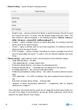
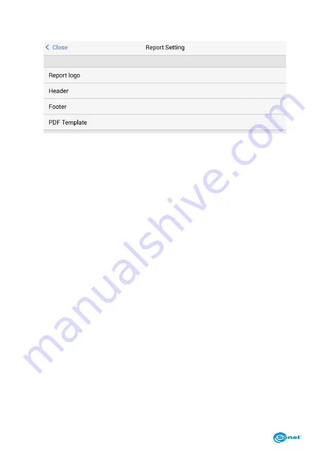
Report Setting 

– opens the report settings window: 


o


‘Report Logo’ – opens a window that allows to select the image that will be used 
as a logo in the report. 

To select, click the desired image and press ‘Done’. The 

files  should  be  placed  manually  in  the  following  directory: 

Internal  memory  \ 

DCIM \ GCamera \ externalPdf \ pdfExternalLogoPic


o


‘Header’ – opens a window (with an on-screen keyboard), for entering a text that 
will be used as the report’s header.  

o


‘Footer’ – opens a window (with an on-screen keyboard), for entering a text that 
will be used as the report’s footer. 

o


‘PDF  Template’  –  opens  a  window  that  allows  to  select  a  template  that  will  be 
used  for  generating  the  report.  To  select,  click  the  desired  template  and  press 
’Done’. 


Stamp setting


– select markers, which, when activated, will be added to images: 

o


‘Date Stamp Setting’ – the date. 

o


„Time watermarking” – image creation time. 

o


‘Emissivity Stamp Setting’ – the values of selected emissivity. 

o


‘Distance Stamp Setting’   – the distance to the object set in the camera. 

o


‘Humidity watermark’ –  the values of selected humidity. 

o


‘Reflectivity temperature stamp setting’ – the values of selected ambient temper-
ature. 

o


‘GPS  watermark’  –  the  GPS  coordinates  that  were  registered  when  taking  pic-
ture. 

o


‘Electronic compass stamp setting’ – compass data. 

o


„Analysis  of  object  temperaturę  watermark”  –  temperaturę  data  for  analysis 
markers set in chapter 7. 

 
Once activated, the markers will be saved into an image file and will be put at the bot-
tom  part  of  an  image  as  its  description  (except  the  LOGO  watermark,  which  will  be 
placed in the upper left part on an image). 

Summary of Contents for KT-560M

Page 1: ...USER MANUAL THERMAL IMAGER KT 560M...

Page 2: ......

Page 3: ...USER MANUAL THERMAL IMAGER KT 560M SONEL S A Wokulskiego 11 58 100 widnica Poland Version 1 01 21 04 2020...

Page 4: ...gn manufacturing and servicing Due the continuous development of our products we reserve the right to introduce changes and im provements in the thermal imaging camera and in the software described in...

Page 5: ...ng and saving images 17 4 1 Manual mode for capturing and saving images 17 4 2 Saving images directly to PC hard drive 18 5 Recording and storing infrared videos 19 5 1 Manual mode for video recording...

Page 6: ...ries 63 16 Connecting the camera to PC 64 16 1 Hardware requirements 64 16 2 Sonel ThermoAnalyze2 Installation Guide 64 16 3 Reading data using USB 64 16 4 Reading data from the SD card using the exte...

Page 7: ...ite or work area Keep the camera steady during operation Do not use the camera in ambient temperatures exceeding its operation and storage temperature ranges Do not direct the camera toward very high...

Page 8: ...m enon NOTE The thermal imager has no parts that could be repaired or modified by its user Never attempt to dismantle or modify the device Opening up the unit invalidates the warranty NOTE Laser locat...

Page 9: ...standard modes like IR infrared visual and PIP picture in picture the cam era has a new mode for mixing images overlapping and blending outlines of the visual image on the infrared image User can tak...

Page 10: ...nder 3 IR video capture button 11 Viewfinder Focus adjustment 4 Focus adjustment buttons T zoom in W zoom out 12 Power On Off button 13 Image mode selection dial 5 Trigger button freeze save image 14...

Page 11: ...cover description in following section 21 View stored photos videos 25 Tripod socket 26 HDMI mini connector 29 LAN RJ45 connector 27 USB micro connector 30 SD card slot 28 Power supply connector 31 B...

Page 12: ...nal information field C The maximum temperature of presented range H Pop up menu D Central point temperature I The camera s setup menu E Emissivity J The minimum temperature of presented range Further...

Page 13: ...witch off procedure 3 2 Displaying image on screen viewfinder During the camera operation in real time mode the image can be displayed on either the LCD screen or in the viewfinder Toggle between thes...

Page 14: ...of the touch screen to switch from the automatic tempera ture mode into the manual mode The shift will be indicated by the padlock icon appearing next to the top and the bottom values of the temperatu...

Page 15: ...clicking the palette bar F on the screen A window with a palette selection options will open The currently selected palette is indicated by a check mark Available palettes the choice may vary dependin...

Page 16: ...cribed in chapter 11 1 Then while in infrared real time mode press C 2 button and the calibration procedure will be carried out 3 8 Laser Pointer Laser pointer can be activated while being in real tim...

Page 17: ...KT 560M USER MANUAL 15 VL visual image MIF infrared image combined with visual image PIP picture in picture both infrared and visual images are displayed...

Page 18: ...rently selected value is indicated by check mark symbol selection window with a circular scrolling list of values Select by moving through the list up and down the selected value is the one between th...

Page 19: ...ll be displayed on screen 4 Saved thermal image file name is IRIxxxxx jpg where xxxxx are digits Addition ally a separate file with a visual image is saved as VISxxxxx jpg where xxxxx is the same numb...

Page 20: ...will proceed to the memory where it is possible to edit the image add annotation create report and send it via the internet Further proceeding is described in details in a following chapters of this m...

Page 21: ...dently just like for the static images 5 1 Manual mode for video recording Recording video to internal memory or to SD card Video recording starts after pressing IR video capture button 3 The commence...

Page 22: ...utton to open up a selection menu that allows to select the file type to be displayed IR images or IR videos click the desired option to se lect it and then close the window by clicking anywhere on th...

Page 23: ...dow will open press OK to delete the file or press Cancel to close the window without deleting it play the recorded video by pressing play button icon In video playback mode af ter touching a screen w...

Page 24: ...h into PDF report editor by clicking the but ton this option is available for IR images to select all files by pressing or to delete all files by pressing the trash bin button Press or Return button 2...

Page 25: ...alysis objects will open up Delete analysis objects all of them by clicking the trash bin icon in pop up menu and confirm your action by pressing OK 7 1 Spot Analysis Press button on Pop up menu to ad...

Page 26: ...Press button on pop up menu to add a line on screen When added the line ap pears in the center of the screen The line can be moved to any place on the screen click and hold down the center part of the...

Page 27: ...ition of the line can be modified rotate lengthen shorten This can be done by changind the position of its endpoints This can be done by pressing and holding the selected end of the line marked and mo...

Page 28: ...oss and for average both crosses are visible Remove the line by clicking the symbol 7 3 Area Analysis Press or button on pop up menu to add an analysis symbol of respectively a rectangle or a circle o...

Page 29: ...nd the position of the object can be modified rotate lengthen shorten This can be done by changing the position of its defining points Press and hold the selected defining point marked and move it to...

Page 30: ...dered as a red cross For the minimum temperature it s rendered as a blue cross and for average both crosses are visible Remove the line by clicking the symbol 7 4 Differential measurement and Delta T...

Page 31: ...side of the screen in the ad ditional information field G If the difference is for the maximum temperatures the result is described as Max Delta for the minimum temperatures as Min Delta and for medi...

Page 32: ...m settings see chapter 11 1 The boundary temperature is dis played on a temperature bar between the maximum and minimum temperatures The boundary temperature change is possible by pressing and holding...

Page 33: ...larged downsized and repositioned on screen to enlarge an image place two fingers on the screen and spread them apart to downsize an image place two fingers on the screen and pinch them close to slide...

Page 34: ...the memory An expandible analysis toolbar can be accessed in the real time mode by pressing the pop up menu button H and choosing Param eter from the selection bar for frozen image by pressing on an a...

Page 35: ...om emis sivity coefficient value can be set by pressing Custom button in the upper part of the opened menu Reflected Ambient Temperature allows to set an ambient temperature reflections of objects tha...

Page 36: ...on voice annotation Adding annotations is possible in the image preview window that can be opened when the image is frozen by pressing on an additional options icon or when viewing imag es after click...

Page 37: ...KT 560M USER MANUAL 35 9 1 Sketch note Start this mode by pressing followed by pressing In this mode any drawing with coloured strokes can be made...

Page 38: ...ines over IR image eraser mode allows to erase parts of lines colour palette change the colour of the drawn lines by clicking se lected dot remove all the changes applied to an image save changes appl...

Page 39: ...this mode a text note can be added using an on screen keyboard Function buttons Save changes and return to the previous screen exit without saving changes 9 3 Voice annotation Start this mode by pres...

Page 40: ...ecorded Stop recording by pressing button Play the recorded annotation by pressing button Other control buttons The track progress slider To change the current playing position drag the track slider l...

Page 41: ...s The report wizard is available in the real time mode by pressing the additional options icon in the thumbnail preview mode for stored images by pressing the PDF report icon in the preview mode for s...

Page 42: ...eld at the bottom of the document field in the document footer After filling in the report a ready document can be created by pressing Generate in the upper right corner of the screen A new window wit...

Page 43: ...communicate with the printer To print a report connect to a WiFi network as described in chapter 11 3 if the printer works in the same network or connect directly to a printer generate a report as de...

Page 44: ...s Preferred the list of printers defined for connection as preferred All all available printers in the camera s range or the Wi Fi networks to which the cam era is connected to Select printing device...

Page 45: ...Copies select the number of copies to be printed Color Mode select between printing in color or in a grayscale Paper Size choose the printout paper size Quality select the printout quality Paper Type...

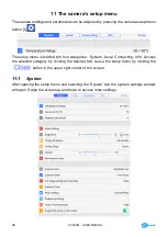
Page 46: ...s divided into four categories System Local Connecting Info Access the selected category by clicking the desired tab Leave the setup menu by clicking the button in the upper right corner of the screen...

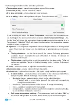
Page 47: ...the auto off function 5 minutes 10 minutes 30 minutes or 60 minutes Timing sleep set the time to put the camera into the sleep mode Following options are available Never to disable the sleep mode 1 m...

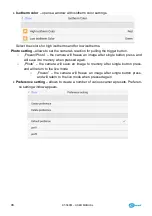
Page 48: ...the camera will freeze an image after single button press and will save it to memory when pressed again o Photo the camera will save an image to memory after single button press and will return to th...

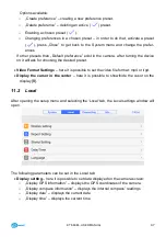
Page 49: ...ed preset Video Format Settings here it is possible to set the video file format mp4 or irgd Display the cursor in the center here it is possible to show hide the cusor on the display B 11 2 Local Aft...

Page 50: ...click the desired template and press Done Stamp setting select markers which when activated will be added to images o Date Stamp Setting the date o Time watermarking image creation time o Emissivity...

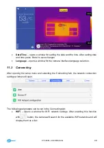
Page 51: ...ace language selection 11 3 Connecting After opening the setup menu and selecting the Connecting tab the network connection settings window will open The following parameters can be set in the Connect...

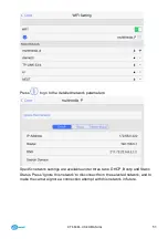
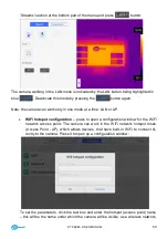
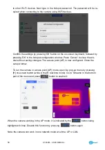
Page 52: ...rm the password by pressing the OK button on the on screen keyboard fol lowed by pressing Join in the Input Password window Press Cancel to close the window without saving changes After establishing c...

Page 53: ...network parameters Specific network settings are available under three tabs DHCP Bootp and Static Status Press Ignore this network to disconnect from the selected network and to make the camera ignor...

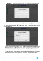
Page 54: ...le in the network at this address sample data below Confirm by pressing the OK button on the on screen keyboard followed by pressing OK in the Ethernet Configuration window Press Cancel to close the w...

Page 55: ...t a time LAN or AP WiFi hotspot configuration press to open a configuration window for the WiFi network access point The camera can work in the WiFi network hotspot mode Access Point AP which allows d...

Page 56: ...ose the win dow without saving changes The access point AP is now configured Close the setup window To run the camera in access point AP mode open the pop up menu by pressing H on screen button while...

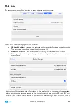
Page 57: ...scribed in chapter 18 Software Version this section shows currently installed firmware version Storage chose this option to open device storage window that allows to select data carrier At the top of...

Page 58: ...not be possible to later determine the exact tempera ture of this area When all the above parameters have been considered then the next important step is to properly configure the measurement paramet...

Page 59: ...the emissivity coefficient is changed or these changes will be performed by processing a thermal image with computer program This value should be changed manually in order to determine proper relation...

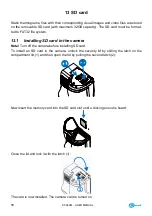
Page 60: ...m 13 1 Installing SD card in the camera Note Turn off the camera before installing SD card To install an SD card in the camera unlock the security lid by sliding the latch on the compartment lid 1 and...

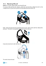
Page 61: ...the security lid by sliding the latch on the compartment lid 1 and then open the lid by pulling the second latch 2 Next insert and press the SD card deeper into its slot until it clicks and then relea...

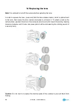
Page 62: ...laced next to the lens then rotate the lens counter clockwise to unmount it To attach a lens to the camera body position the lens in the camera s lens mount and mount the lens by rotating the lens clo...

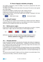
Page 63: ...2 Battery power supply During camera operation the battery charge level is being shown in real time in A infor mation area in upper left corner of the screen as below changing symbol max min Addition...

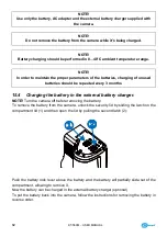
Page 64: ...3 months 15 4 Charging the battery in the external battery charger NOTE Turn the camera off before removing the battery To remove the battery from the camera unlock the security lid by sliding the la...

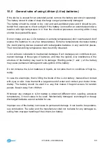
Page 65: ...ges Such damages can contribute to per manent damage of those type of batteries and thus the ignition Any interference in the structure of the battery may lead to its damage Shorting poles and of the...

Page 66: ...meras and then install ThermoAnalyze2 The installation wizard will initiate Necessary system modules of Microsoft will get in stalled first followed by Sonel ThermoAnalyze2 software Follow the on scre...

Page 67: ...on the PC The drivers will install automatically When completed the camera will appear as a portable device new disk drive named SABRESD MX6DQ Double click the SABRESD MX6DQ to open a window with avai...

Page 68: ...gnized as another drive on your PC the name of the drive will be the same as the SD card s name The thermogram files are located in the following directory the drive let ter DCIM Copy selected or all...

Page 69: ...KT 560M USER MANUAL 67 Select Change adapter settings in the Network and Sharing Center window...

Page 70: ...68 In the adapter settings window right click on the Ethernet icon and then select Proper ties The Ethernet Properties window will open Select the Internet Protocol Version 4 TCP IPv4 from the list a...

Page 71: ...ttings of the camera chapter 11 3 and the LAN network if the camera and the PC are both connected to the existing LAN network When the above parameters have been set press OK The network connection wi...

Page 72: ...USB and enter IP address set in accordance to the description in chapter 11 3 Press Confirm The camera image is now transmitted live to your PC In the bottom left corner of the screen the camera stat...

Page 73: ...the user manual of the Sonel Thermo Analyze2 software 16 6 WiFi connection hotspot mode The camera can be connected directly to PC via Wi Fi network Turn on the camera and configure the Wi Fi hotspot...

Page 74: ...ect In the connection window enter the password set in the camera Press OK to save and the computer will establish the wireless connection with the cam era Run Sonel ThermoAnalyze2 software and go to...

Page 75: ...r PC In the bottom left corner of the screen the camera status has now turned into Connected Click Close at the bottom of the screen to disconnect The camera s on line operation im age capturing savin...

Page 76: ...port 26 on the camera As a signal port select the HDMI port that has been used to connect with the camera on the signal receiving device 18 Firmware update NOTE Do not switch off the camera s power s...

Page 77: ...re During the update procedure following screen is displayed When the firmware has been installed the following screen is displayed To complete the update procedure press Done button The camera will c...

Page 78: ...emperature Alarm Visual and voice Palettes 8 Image file format JPG or raw data Reports module PDF reports report printing via Wi Fi Video file format H 264 with temperature data Video internal storage...

Page 79: ...be used for cleaning the optical viewfinder and particularly op tics and accessories of the camera Use a clean dry and soft cloth for cleaning the body of the viewfinder for cleaning the lens use onl...

Page 80: ...er includes Thermal imager Lens cover 2 x Li ion battery 11 1 V 2 9 Ah WAAKU18 SD card 16 GB WAPOZSD16 Shoulder harness WAPOZPAS3 microUSB cable WAPRZUSBMICRO HDMI cable WAPRZHDMI LAN cable RJ45 WAPRZ...

Page 81: ...o used up electrical or electronic equipment Before delivering the equipment to the collection centre do not attempt to dismantle any of its parts NOTE Follow local regulations related to disposing of...

Page 82: ...o luxmeters The Calibration Certificate is a document that presents a relation between the calibration standard of known accuracy and meter indications with associated measurement uncertainties The c...

Page 83: ......

Page 84: ...SONEL S A Wokulskiego 11 58 100 widnica Poland tel 48 74 858 38 60 fax 48 74 858 38 00 e mail sonel sonel pl www sonel pl...

Reviews: