background image


USER MANUAL  

37 

11. Camera's Driver and Sonel ThermoAnalyse PC Installation 

Guide. 

The driver and the PC program can be installed on Microsoft® Windows (XP and higher) 
operating system (x86, x64). KT-640 driver installs as an additional network interface card.   

11.1.  Windows XP installation guide 

To  install  the  camera  on  Windows XP use the driver supplied with the camera on CD or 
download it from www.en.sonel.pl.  
Turn on the camera and wait antil self test procedure is completed, and then connect the 
camera to USB port on computer.  
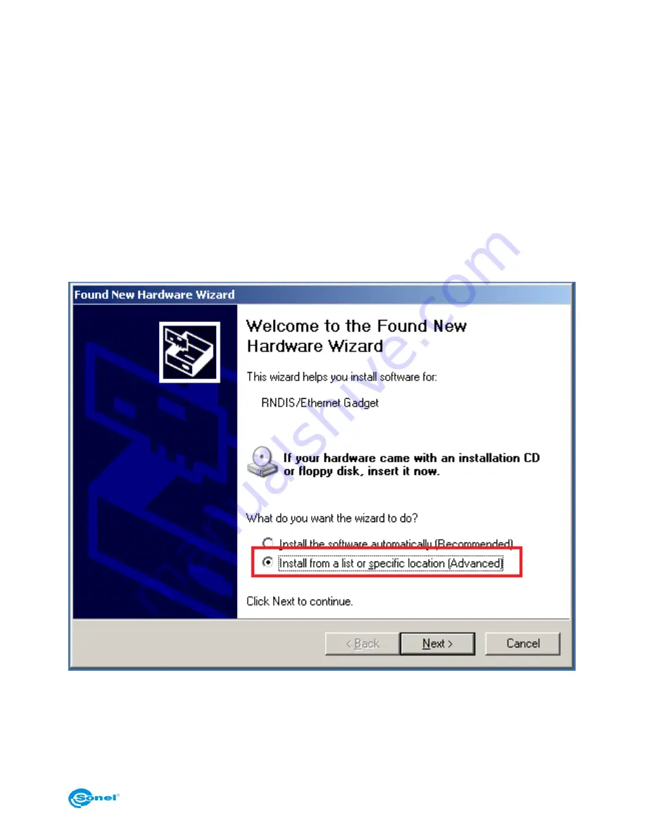
Computer will detect new hardware: 


Choose "install from a list or specific location" and then select to search the driver is  se-
lected location:: 

Summary of Contents for KT-640

Page 1: ...USER MANUAL THERMAL IMAGER KT 640 SONEL S A ul Wokulskiego 11 58 100 widnica version 1 1 09 09 2014...

Page 2: ...oducts of Sonel S A are manufactured in accordance with Quality Management System which is approved to ISO9001 2008 for the design manufacturing and servicing Due the continuous development of our pro...

Page 3: ...h temperatures filter 11 4 5 EMISSIVITY 12 4 6 LED FLASHLIGHT 12 4 7 MANUAL CALIBRATION 13 4 8 SELECTING THE COLOUR PALETTE 13 4 9 LASER POINTER 15 4 10 IMAGE MODES 15 5 CAPTURING AND SAVING IMAGES WI...

Page 4: ...INSTALLATION GUIDE 37 11 1 WINDOWS XP INSTALLATION GUIDE 37 11 2 WINDOWS 7 INSTALLATION GUIDE 42 11 3 WINDOWS 8 INSTALLATION GUIDE 48 11 4 SONEL THERMOANALYZE INSTALLATION GUIDE 61 12 RECORDING INFRA...

Page 5: ...rk area Keep the camera steady during operation Do not use the camera in ambient temperatures exceeding its operation and storage temperature ranges Do not direct the camera toward very high intensity...

Page 6: ...cted Then you need to press and hold C button for 2 seconds calibration procedure will be per formed and it will be indicated by calibration note on screen During imager operation its housing temperat...

Page 7: ...he image with Joystick 11 In order to have both thermal and real time image projected on large screen 1 and to have easy access to advanced functions attach it by the grip to the socket on the upper s...

Page 8: ...e moved in both up down and left right axis Joystick operation depends on the currently running function 3 2 Viewfinder touch screen TV output During the camera operation in real time mode infrared im...

Page 9: ...e camera in PAL or NTSC depends on the video output settings selected in System Settings menu section 8 3 3 3 On screen information arrangement Bottom bar contains real time clock current mode status...

Page 10: ...the same on the appearing icon to make the drop down menu expand It contains a list of functions their settings and parameters Menu functions are grouped into 4 sections Navigating through the Menu i...

Page 11: ...en the camera is in the real time mode and when a real time infrared image is being displayed on screen Press 6 button or click on icon or on the temperature value on icon on the touch screen to switc...

Page 12: ...d in section 8 2 Whilst clicking on emissivity coefficient symbol on icon or after selecting this function from main menu the list of the most common materials with their emissivity coefficient values...

Page 13: ...u see section 8 3 4 7 Manual calibration During operation the camera runs periodic auto calibration procedure it is signalled by the closing shutter sound and the Calibration word appearing on the bot...

Page 14: ...SONEL KT 640 THERMAL IMAGER 14 Available colour palettes 1 2 3 4 5 6 7 8...

Page 15: ...s Thermal image mode can be switched into visual image mode at any time while being in real time mode or by freezing thermal image on screen button and also during browsing thermal images stored in th...

Page 16: ...inserted the camera will display infrared images in real time mode and image can also be freezed or being analysed however it is not possible to store it in the memory The lack of SD card is indicated...

Page 17: ...e and moving pen up and down in struction on how to change emissivity coefficient values is described in section 4 5 NOTE The value selected for the captured image will also remain active after re tur...

Page 18: ...ingle extended jpeg file as well temperature of each and every pixel of thermal image voice note and mark flag symbol described above 2 editing thermal image in software other than Sonel ThermoAnalyse...

Page 19: ...memory card Click on the symbols located on the bottom bar to go to the list of saved static thermal images go to the list of saved infrared video files and to toggle between screens with saved files...

Page 20: ...therm analysis see below deleting of active area object of analysis Remaining icons available on the bar depending on the image mode we re in execute the functions described in previous sections Press...

Page 21: ...on screen with one end marked by yellow square and the other end with temperature indication in rectangle shaped box De pending on the options selected in analysis settings see section 8 1 it can dis...

Page 22: ...ea with its temperature on screen Depending on the options se lected in analysis settings see section 8 1 it can display maximum average or maxi mum temperature within the area When the maximum or max...

Page 23: ...en images Slide markers on temperature bar to set the temperature range for which isotherm area will be marked with black white or green colour depends on analysis settings see sec tion 8 1 Isotherm t...

Page 24: ...n the selected temperature alarm see TempAlarm AnalysisFunction Select the temperature that will be displayed during line or area analysis average maximum or minimum TempAlarm Audible alarm that will...

Page 25: ...surement is made allows you to set the proper relation between ambient temperature and the measured objects and it allows to adjust the temperature reading This feature is useful when measurements are...

Page 26: ...captured frames 2 4 8 or 16 in case of selecting the parameter s value above 1 it is advised to use tripod as all vibrations caus ing even the slightest movement of the camera result in degrading the...

Page 27: ...go to section 2 and select with touch pen or Joystick De fault tab And then confirm the action in the window below Default settings laser pointer LED flashlight Auto Power Off Power alarm and tem per...

Page 28: ...8 7 Video recording infrared video recording procedure has been described in details in section 11 1 8 8 WiFi This function allows to set the camera to work wirelessly Network to which the camera will...

Page 29: ...orks found will be displayed in the window Select the line containing desired network with a stylus and additional window with IP address will appear The IP address should be used in Sonel ThermoAnaly...

Page 30: ...AL IMAGER 30 Select the camera type KT640 WIFI and in the window below type obtained IP address Connection with computer will be set and the image from the camera will be displayed di rectly in the pr...

Page 31: ...reen 8 10 Information on hardware and firmware version Info option displays information on the hardware and the firmware version used in the camera on the bar at the top of the screen 8 11 Firmware up...

Page 32: ...oper especially during op eration in low temperature or measurements from a location of temperature differing from ambient temperature of the examined object In order to maintain accuracy of measure m...

Page 33: ...or 22 flasher green red alter nately for few seconds During camera operation LED indicator 22 is off During camera operation the battery charge level is being shown in real time in lower right corner...

Page 34: ...battery from the camera pull the battery comprtment cover s 8 prong 26 and open the battery compartment cover Push the battery lock lever 27 above the battery and the battery will partially slide out...

Page 35: ...g nor mal operation camera works until reaching certain point of discharge Reaching this point is when the charging should be performed in the camera or in external charger Memory effect occurs in Ion...

Page 36: ...increase of the battery temperature In this case the battery will not be fully charged to reach its full capacity Do not charge and use LoOn batteries in extreme temperatures Extreme temperatures decr...

Page 37: ...ork interface card 11 1 Windows XP installation guide To install the camera on Windows XP use the driver supplied with the camera on CD or download it from www en sonel pl Turn on the camera and wait...

Page 38: ...SONEL KT 640 THERMAL IMAGER 38 Driver installation will begin Information suggesting that the driver is not compatible with our operating system Ignore it and press Continue anyway...

Page 39: ...USER MANUAL 39 Go to Start menu or select Network Connections in Control Palen and select Network Connections...

Page 40: ...640 THERMAL IMAGER 40 In the window that opens select the connection that uses installed Acme USB Remote NDIS Network device Go to Properties and select Internet Protocol TCP IP and then select its pr...

Page 41: ...USER MANUAL 41 click on Use the following IP address and type in IP address see below Click OK and the camera is ready to work with Windows XP operating system...

Page 42: ...til self test procedure is completed and then connect the camera to USB port on computer Open Device Manager right click on My Computer on desktop and choose its Proper ties from drop down menu or ope...

Page 43: ...USER MANUAL 43 or through Hardware and Sound section Open Device Manager and find RDNIS Ethernet Gadget in Other Devices tab Right click on it and select Properties and then Update Driver...

Page 44: ...let me pick from select Network Adapters and then select producer choose Microsoft Corporation Microsoft in some cases network adapter Remote NDIS Compatible Device Confirm your selection in Device M...

Page 45: ...USER MANUAL 45 Go to Open Network and Sharing Center in Sontrol Panel or through shortcut on task bar Go to change adapter settings...

Page 46: ...SONEL KT 640 THERMAL IMAGER 46 Select connection using USB Ethernet RDNIS Gadget Right click and select Properties chose Internet Protocol Version 4 and click on its Properties as below...

Page 47: ...USER MANUAL 47 Type in IP address as below Press ok and data from the camera can be transferred to computer...

Page 48: ...s 8 installation guide Before installing on Windowds 8 it is required to switch it into mode allowing instal lation of anouthorised drivers 1 Move mouse cursor to lower right corner of screen and sele...

Page 49: ...USER MANUAL 49 3 in the next window select General and then Restart now 4 go to Troubleshoot...

Page 50: ...SONEL KT 640 THERMAL IMAGER 50 5 go to advanced options 6 select Startup settings...

Page 51: ...n keyboard and the system will reboot in the mode al lowing unauthorized drivers installation Proper driver installation Turn on the camera and wait antil self test procedure is completed connect the...

Page 52: ...SONEL KT 640 THERMAL IMAGER 52 Depending on the control Panel configuration you can open Device Manager directly or through Hardware and Sound...

Page 53: ...USER MANUAL 53 See below In Device Manager wingow find Other Devices with RNDIS Ethernet Gadget in it Right click on it and select PropertiesGo to Driver tab and select Update driver...

Page 54: ...SONEL KT 640 THERMAL IMAGER 54 And select an option as below...

Page 55: ...USER MANUAL 55 Choose let me pick option as below And then select producer Microsoft Adapter Remote NDIS compatible Device...

Page 56: ...SONEL KT 640 THERMAL IMAGER 56 Ignore the wwarning and click Yes to confirm Proper installation will be confirmed as below...

Page 57: ...USER MANUAL 57 In device manager another network adapter will appear USB Ethernet RNDIS Gadget After finishing installation go to Desktop...

Page 58: ...SONEL KT 640 THERMAL IMAGER 58 Go to the bar in low right corner and select open Network and Sharing Center...

Page 59: ...dapter settings Chose network connection linked to USB Ethernet RNDIS Gadget Right click on selected network connection and select Properties In Networking tab find and select Internet Protocol Verisi...

Page 60: ...SONEL KT 640 THERMAL IMAGER 60 Go to Use following IP address and type fil lit in as below Click OK to accept changes and the connection will be configured properly...

Page 61: ...folder After selecting language new dialog box will appear Choose thermal cameras and then install ThermoAnalyze Installation process will begin follow the on screen instructions NOTE 1 Without chang...

Page 62: ...n be selected by in main Menu or through expandable tool bar or by pressing button and finally by pressing and holding button for 2 seconds Select this function to make video recording window appear o...

Page 63: ...to recording infrared video are described below Detiled description of all features and functions can be found in Sonel ThermoAnalyze user manual Setup option File menu is used to determine the direct...

Page 64: ...ame will be stored In some situations there is no need to capture all frames Using this option allows to save space on hard drive SD card Update track view frequency of refreshing information for each...

Page 65: ...window Starts online preview in Device Video mode Click to play recorded video Stops online preview in Device Video mode Click to pause recorded video Forwarding the video frame by frame in playback m...

Page 66: ...and Allows to choose which palette will be used to render real time infrared images Nine pal ettes are available Palette can also be changed in image palette window when it s not displayed press on to...

Page 67: ...Optimal settings can be restored at any time by pressing Cancel button or Auto see above Note Adjustment bar appears and disappears also upon double mouse click at any place within the thermal video...

Page 68: ...isplay diagram being drawn in real time representing tempera ture fluctuation of spot lines or areas added to the infrared video For spot it will display its current temperature For lines or areas it...

Page 69: ...r with the object it represents Thanks to the fact that the chart line color depends on the object color you can analyze the change of tem perature of many spots and areas in one window Press F11 to s...

Page 70: ...able in Video mode Tools Menu Temperature Alarm Audible alarm sounds whenever temperature set point is exceeded Alarm Setting set the limit temperatures crossing which activates an alarm Set Max value...

Page 71: ...Data Command Use this command to export real time temperature data analysis results into txt file or chart The data can be displayed as point line or surface chart according to selected time interval...

Page 72: ...he combination of infrared and visual image picture in picture with the ability to combine images only for the specific tempera ture range Measurement Temperature Range Filter 1 20 250 Filter 2 200 80...

Page 73: ...ield replaceable Charging System In camera or in battery charger Battery Operating Ti me Over 2 hours continuous operation External Power Opera tion AC 110 230 VAC 50 60Hz 9V DC Environmental Specific...

Page 74: ...SONEL KT 640 THERMAL IMAGER 74 Size 186mm 106mm 83mm Standard Model Housing Magnalium Tripod interface 1 4 20...

Page 75: ...5 copper oxidized black 0 88 copper polished 0 07 copper polished annealed 0 01 0 02 brass 0 10 brass oxidized 0 61 nickel polished 0 05 lead polished 0 08 lead grey 0 28 lead oxidized 0 63 paper whit...

Page 76: ...ng cloth 17 Calibration In order to ensure the accuracy and reliability of the thermal imaging camera it is recom mended to calibrate the instrument once every 12 months For detailed information relat...

Page 77: ...upplied by the manufacturer includes 1 KT 640 Thermal Imager 2 Detacheable VGA touch screen 3 Lithium rechargeable battery 2 pcs 4 External battery charger with AC adapt er 5 RS232 TV interface 6 VGA...

Page 78: ...c equipment Before delivering the equipment to the collection centre do not attempt to dismantle any of its parts NOTE Follow local regulations related to disposing of packaging used up batteries and...

Reviews: