LKZ-1500-
LITE ● LKZ-1500 – USER MANUAL
10
3.4.2
Direct connection
– galvanic mode
3.4.2.1 Connecting the transmitter to the object
WARNING
Verify that the line to be tested is not at live voltage. Load connection to the trans-
mitter output is allowed only when the transmitter is switched off. The transmitter
direct connection to the examined live line is prohibited.
Socket shall be connected to ground pin driven into the ground at a distance of 5-10 m from the
route of the object. To increase the survey current, ground pin shall be earthed at a maximum depth.
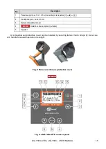
Connect the blue wire to the output socket of the transmitter
(Fig. 2 p. 14). The other end of the
cable, using a blue crocodile, should be fastened to a pre-grounded grounding probe. Use the red
wire to connect the output socket of the transmitter (Fig. 2 p. 13) to the conductive part of the object
(see
).
In the search for unearthed object, for example, gas pipeline or cable, it is preferable to earth the
object at far end (see
– it will provide maximum survey current. Otherwise, current will leak off
the ground through isolation capacitance and its level will decrease. As a result it will reduce possible
search range.
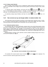
Fig. 3 Connection the transmitter to the
metal pipeline.
Fig. 4 Connection to cable armour (shield), to
one of the cords in case of unshielded cable or
to metal section of insulated pipeline
There are other methods of transmitter connection to objects or cables depending on the purpos-
es, for example, in case of insulation fault tracing. For more information see the section on Working
with A-frame.
3.4.2.2 Signal frequency selection
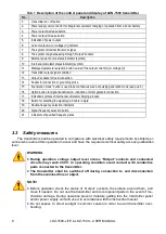
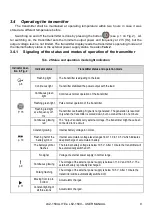
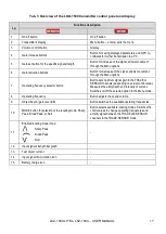
Turn on the transmitter and set the desired output frequency, power, and operating mode . In ad-
dition, with the button
select the signal output from the transmitter's output sockets. The symbol
will appear on the display. Selection depends on particular search conditions and current task
and requires acquisition of practical skills by an operator.
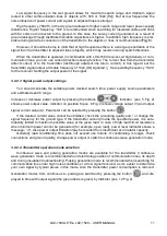
Signal frequency selection is made by pressing the button
and is frequency-loop : 273
→
1024 → 8928 → 33k → 273, etc. (see position 1 in Fig. 2).
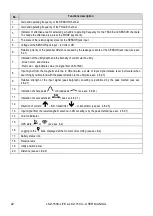
Double frequency signal is made by the
key with an indicator
↑↓
for double frequency 1024 [Hz]
and
φ
for double frequency 8928 [Hz].
Summary of Contents for LKZ-1500
Page 1: ......
Page 2: ......
Page 18: ...LKZ 1500 LITE LKZ 1500 USER MANUAL 16 Fig 10 LKO 1500 receiver panel...
Page 30: ...LKZ 1500 LITE LKZ 1500 USER MANUAL 28 Fig 25 Locating with Compass line...
Page 57: ...LKZ 1500 LITE LKZ 1500 USER MANUAL 55 NOTES...
Page 58: ...LKZ 1500 LITE LKZ 1500 USER MANUAL 56 NOTES...
Page 59: ......
Page 60: ......


