LKZ-1500-
LITE ● LKZ-1500 – USER MANUAL
11
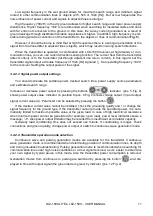
Low signal frequency in the wet ground allows for maximum search range and minimum signal
routed to other communication lines or objects (273, 526 or 1024 [Hz]). But at low frequencies the
noise influence of power current and signals in adjacent lines is stronger.
High frequency (“8928”) in the dry ground allows for higher search range and lower power-supply
disturbance. Higher frequency “33k” is recommended when searching for insulated cables and lines
with far ends not connected to the ground. In this case, the survey current generated as a result of
ground leakage through distributed isolation capacitance is higher. In addition, high frequency is pref-
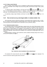
erable during wire-free connection of the transmitter to the objects or lines of communication (
However, it should be borne in mind that at high frequencies there is a stronger penetration of the
signal from the transmitter to adjacent lines (objects), which may results in wrong search directions.
When the transmitter is operated in combination with LKO-1500 receiver, at high density of com-
munication lines, you can use current direction sensing function. The current flow from the transmitter
(direct current) or to the transmitter (let-through adjacent line return current). In this regard, set the
transmitter signal output at double frequency of 1024 [Hz] signaled
↑↓
. Set operating frequency “1024”
for the receiver. Setting the output power of the signal.
3.4.2.3 Signal power output settings
You should correlate the settable power, desired search time, power supply source parameters
and estimated search range.
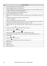
Increase or decrease power output by pressing the buttons
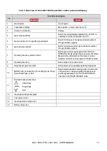
. Indicator (pos. 5 Fig. 2)
shows power output value. Indicator on position 6 (pos. 6 Fig. 2) shows voltage output (V) and output
signal current value (А). Parameter can be selected by pressing the button
.
If the desired current value cannot be obtained, check the grounding quality and / or change the
signal frequency for the ground type. If the transmitter cannot provide the specified power, it is auto-
matically limited to maximum possible value at the given load. In case of high load circuit resistance
when minimum power cannot be generated (for example, open load), power level indicator shows a
message: “
-1
”. Also power output limitation may be resulted from insufficient accumulator capacity.
Generally load conditioning time does not exceed one minute. If conditioning is longer, check
connections and ground quality, change power output or switch to continuous wave generation mode.
3.4.2.4 Transmitter operation mode selection
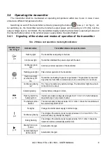
Continuous wave and pulsing generation modes are available for the transmitter. Continuous
wave generation mode is recommended when determining position of communication lines, its depth
and during insulation troubleshooting. Pulsing generation mode is recommended when searching for
communication line under high noise conditions or at low signal received, as it’s easier to determine
your own signal by typical pause in this mode. Also the transmitter power consumption is reduced.
Generation modes from continuous to pulsing are switched by pressing the button
and dis-
played in time with output signal (the green diode is green) by indicator (pos. 12 Fig. 2).
Summary of Contents for LKZ-1500
Page 1: ......
Page 2: ......
Page 18: ...LKZ 1500 LITE LKZ 1500 USER MANUAL 16 Fig 10 LKO 1500 receiver panel...
Page 30: ...LKZ 1500 LITE LKZ 1500 USER MANUAL 28 Fig 25 Locating with Compass line...
Page 57: ...LKZ 1500 LITE LKZ 1500 USER MANUAL 55 NOTES...
Page 58: ...LKZ 1500 LITE LKZ 1500 USER MANUAL 56 NOTES...
Page 59: ......
Page 60: ......


