LKZ-1500-
LITE ● LKZ-1500 – USER MANUAL
25
The
sharp peak
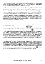
method provides high accuracy of the utility tracing since the signal peak near
the line axis is on the abrupt area of the graph (see
, left display). When the antenna is ar-
ranged right over the axis of the utility, the responding signal will be on its peak. The signal gain in this
point shall be set so that ¾ of the scale were lighted; the sound volume shall be adjusted at the level,
comfortable for the operator. The
button may be used to adjust the optimum gain of each spe-
cific signal automatically. The indicator bargraph will grow down when the Receiver moves away from
the axis. Further displacement of the Receiver will result in disappearing of the linear scale. The --.
–
icon will appear instead of the signal level indication.
If the signal is weak or the depth of utility is sufficient, the indication on the Peak scale may be un-
stable or missing. In this case you shall use the
broad peak
method which demonstrates higher sen-
sibility to weak signals.
The indicator scale readings do not depend directly on the location of the Receiver towards the
utility at the
broad peak
method since the signal peak is within the broad area of the graph ( see
, right display). However, this method provides maximum sensitivity of the Receiver.
As far as you move along the line, the Receiver gain and the sound volume shall be adjusted de-
pending on the strength of the received signal. Along the route the signal strength may change de-
pending on the cable core twists. The strength of signal may also drop considerably in the areas
where the cables are laid under pipelines or near connecting sleeves, or in the areas where they are
shielded with metal pipes.
4.6.2.2
Peak search with 1:4 scale
In some cases, the peak scale is not sufficient, e.g. when the pipeline branch of smaller diameter
is traced deeply under the ground. At that, some portion of tracing current leaks through the branch,
and the peak signal strength over the main pipeline drops slightly, and this may go unnoticed.
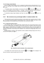
The option of the peak scale extension may be selected by scrolling the MENU options as fol-
lows:
Menu > Indication > Trace > Peak type > Zoom 1:4
). The option reduces the scale
divisions to increase its resolution. The
icon will be displayed, a yellow strip will appear under
the peak scale to show the expansion bar graph relative to the normal (unexpanded) scale.
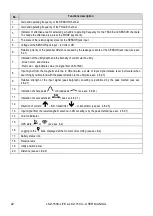
Using the gain up/down buttons
, place the end of the extended “peak” bar graph
within the visible area of the display. The gain-up button is expands the scale. The gain-down button
makes the scale shorter.
The optimum gain and scale for a specific signal intensity may be obtained by pressing the
button.
Summary of Contents for LKZ-1500
Page 1: ......
Page 2: ......
Page 18: ...LKZ 1500 LITE LKZ 1500 USER MANUAL 16 Fig 10 LKO 1500 receiver panel...
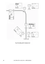
Page 30: ...LKZ 1500 LITE LKZ 1500 USER MANUAL 28 Fig 25 Locating with Compass line...
Page 57: ...LKZ 1500 LITE LKZ 1500 USER MANUAL 55 NOTES...
Page 58: ...LKZ 1500 LITE LKZ 1500 USER MANUAL 56 NOTES...
Page 59: ......
Page 60: ......

