LKZ-1500-
LITE ● LKZ-1500 – USER MANUAL
35
4.7.2
Testing of ground plots with LKN transmitter
To improve the location reliability it is recommended to trace the utility with the signals generated
by the Transmitter either with galvanic coupling or with the internal transmitter antenna.
During the current search line excitation, you should take into account that:
the high Transmitter power and small distance from the inductors to the Receiver cause
strong direct connection, that will drown the utility signals;
the strength of current induced in the utility line by means of the inductors will be much lower
than that at the direct connection;
the strength of current induced in the utility line by means of the inductors will be high at high
operating frequencies of the Transmitter and close location of the inductor to the utility line;
the utility current strength depends on the grounding on the ends of the utility line. If one of
the ground contacts is missed, the location will be difficult, so the Transmitter shall be set on
the maximum frequency to increase the currents via the capacity between the utility and
ground.
4.7.2.1 One-man test method
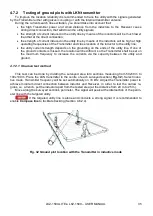
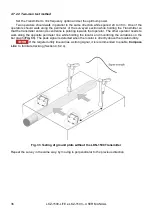
This test can be done by dividing the surveyed area into sections measuring from 50x50 m to
100x100 m. Place the LKN transmitter in the centre of each surveyed section (
). Select induc-
tive mode. Transmitter frequency will be set automatically on 33 kHz. Adjust the Transmitter power to
achieve minimum direct connection between inductor and Receiver. In order to test the narrow re-
gions, i.e. a trench, put the inductor apart from the tested area (at the distance from 20 m to 25 m).
Move along the surveyed section's perimeter. The signal will peak at the intersection of the perim-
eter line with the targeted utility.
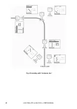
If the targeted utility line is alone and conducts a strong signal, it is recommended to
enable
Compass line
to facilitate tracking (Section 4.6.2.4).
Fig. 32 Ground plot location with the Transmitter in inductive mode
Summary of Contents for LKZ-1500
Page 1: ......
Page 2: ......
Page 18: ...LKZ 1500 LITE LKZ 1500 USER MANUAL 16 Fig 10 LKO 1500 receiver panel...
Page 30: ...LKZ 1500 LITE LKZ 1500 USER MANUAL 28 Fig 25 Locating with Compass line...
Page 57: ...LKZ 1500 LITE LKZ 1500 USER MANUAL 55 NOTES...
Page 58: ...LKZ 1500 LITE LKZ 1500 USER MANUAL 56 NOTES...
Page 59: ......
Page 60: ......


