LKZ-1500-
LITE ● LKZ-1500 – USER MANUAL
37
5
Methods of locating damaged pipelines and utilities
The methods below are based on identification of relative distortions of signals within the dam-
aged areas.
Sometimes these distortions are unobservable so all the readings obtained during
measurement shall be stored in the PC memory for further analysis (see sec. 6).
5.1
Fault finding with leakage current
This method should be used to locate broken insulation of pipelines or utilities with considerable
leakage to ground. If a sudden drop of the current strength is revealed in the areas without tie-in con-
nections and branches, this will mean that a considerable damage of the line insulation takes place.
This method
is true for high initial current (≥0,5 A) and considerable drop of current strength after the
damaged area. We recommend you to make tracing on the frequencies of:
1024 Hz,
273 Hz or 526 Hz.
5.2
Fault finding with insulation control sensors
–
DKI-E or A-frame
Contact sensors of insulation control A-frame, and non-contact sensors DKI-E are used for loca-
tion. Turn the Receiver into the “
Trace-SENSOR
” mode. The sensors shall be connected to the
“SENSOR” jack (Pos. 4 in
).
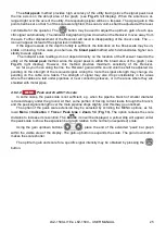
The broken areas are detected according to the strength of the signal from the sensors on the
SENSOR scale. Verification of the utility position control shall be performed with the “peak” and “null”
methods (See
). If the
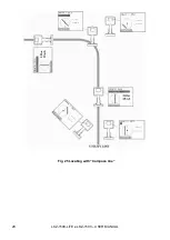
Compass
function is activated, locating will be performed by the posi-
tion of the utility pointer relative to the Receiver (See
). Always control the depth of the utility
and the strength and direction of current to avoid false trials (the current direction shall be controlled
when
two-frequency signal of 1024 Hz
is set on the transmitter).
To adjust the line scale of the signal strength from the insulation control sensors, set the
pointer (Pos. 3 in
) to the
SENSOR
position by pressing the
button. The gain
may be selected with the gain up/down arrows. For the automatic gain selection use the
but-
ton.
NOTE!
Do not supply the voltage of more than 42 V to the SENSOR jack inputs.
Summary of Contents for LKZ-1500
Page 1: ......
Page 2: ......
Page 18: ...LKZ 1500 LITE LKZ 1500 USER MANUAL 16 Fig 10 LKO 1500 receiver panel...
Page 30: ...LKZ 1500 LITE LKZ 1500 USER MANUAL 28 Fig 25 Locating with Compass line...
Page 57: ...LKZ 1500 LITE LKZ 1500 USER MANUAL 55 NOTES...
Page 58: ...LKZ 1500 LITE LKZ 1500 USER MANUAL 56 NOTES...
Page 59: ......
Page 60: ......


