LKZ-1500-
LITE ● LKZ-1500 – USER MANUAL
38
5.2.1
Insulation fault finding by signal drop
A-frame
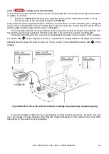
– drive both A-frame sensors into the ground.
DKI-
Е probe
– two operators must walk
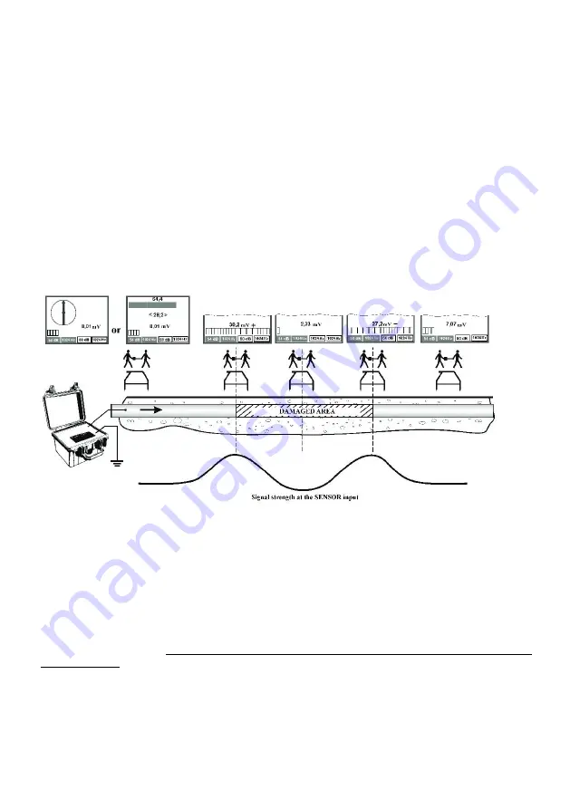
about the surveyed area one behind another along the utility’s centreline (
). The beginning of
the insulation fault point can be determined by:
a rise of the signal strength when one of the sensors/one of the operators is directly above the
fault location;
with the null signal reading if the fault being pinpointed is between the A-frame sensors/the
operators.
If the indications are partial to coming close to the fault location, narrow the spacing of the test points.
Note that if the fault is extensive, there is a null (minimum) signal strength area between the signal
peak readings. This null area can potentially be the location of a fault.
For a more precise and easy insulation fault location, you can use the SENSOR input signal po-
larity test. It is done by switching the Transmitter to generate the 1024 Hz double-frequency signal
and the Receiver to 1024 Hz operating frequency on the SENSOR input. When the double-frequency
signal strength reaches a predefined threshold, the signal polarity indicator comes on (item 6 in
Fig. 34 Connection diagram and the signal strength when locating an insulation fault by detec-
tion of the signal loss at the polarity sign changeover
When the operator moves along the undamaged part of the utility, and then moves directly over
the damaged area, the chaotic change (or missing) of polarity at the SENSOR input may occur be-
cause of weak signal (
). As far as the operator approaches the bound of the damaged area,
and the signal increases, the polarity becomes stable (plus or minus sign, depending on direction of
current inducement) When the operator passes the border of the damages area, the polarity will
change (from "+" to "-" or vice versa). In case the insulation is damaged in one point only, the signal
level over the damaged point will have a sharp null.
Keep in mind that the polarity inversion without a specific signal fluctuation may not be considered
as a sign of fault.
Summary of Contents for LKZ-1500
Page 1: ......
Page 2: ......
Page 18: ...LKZ 1500 LITE LKZ 1500 USER MANUAL 16 Fig 10 LKO 1500 receiver panel...
Page 30: ...LKZ 1500 LITE LKZ 1500 USER MANUAL 28 Fig 25 Locating with Compass line...
Page 57: ...LKZ 1500 LITE LKZ 1500 USER MANUAL 55 NOTES...
Page 58: ...LKZ 1500 LITE LKZ 1500 USER MANUAL 56 NOTES...
Page 59: ......
Page 60: ......


