background image

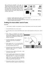
in figure). This indicates that the damage is located in 
front of you. 


IMPORTANT:  During  the  detection  process,  A-frame 

and the receiver should face the same direction (shown 

by the arrow on A-frame and the receiver).


Finding faults 

Known cable route 


After determining the direction of the damage, LKO-2000 receiver will display strength and direction of the signal 
if the signal is strong  enough. If not,  increase the  power of the transmitter and  repeat  the steps described in 
section "Setting the transmitter and A-frame". If the signal is not detected, the detector will display "- - -" in the 
middle of the screen. 


1.  Move 3 meters along the cable route and again drive A-frame into the ground. 
2.  When the arrows indicate the opposite directions, take a step back and drive again A-frame into the 

ground. 

3.  Repeat step 2, moving on shorter distances, until the arrow changes its direction after moving only by a few 

centimeters. The location where the movement of the A-frame changes the direction of the incoming signal 
is the place of the damage (between probes of A-frame). 

4.  Turn A-frame 

by 90° and repeat the location procedure, until the arrow changes its direction after a slight 

movement. Damage is located directly between the probes. 


Unknown cable route


IMPORTANT: 

  If  possible,  locate  the  cable  route  earlier  using  the  receiver  and  mark  its  location.  Then, 

follow the instructions valid for the known route of the cable. 


1.  Draw a straight line between the two disconnected ends (1, 4) of the insulated cable. 
2.  Follow the instructions in "Known cable route" (above). 
3. 

After detecting the fault (2) at the straight line, turn the probe by 90° and find the actual location of the 
damage (3). 


Summary of Contents for LKZ-2000

Page 1: ...LKZ 2000 Operator s Manual Issue 1 2...

Page 2: ...SONEL S A Wokulskiego 11 58 100 widnica Poland tel 48 74 858 38 60 fax 48 74 858 38 09 E mail export sonel pl Web page www sonel pl Note Service repairs must be performed only by the manufacturer...

Page 3: ...LKZ 2000 Operator s Manual Overview 3 Overview Chapter Contents Serial Number Location 4 System Components 5 Intended Use 6 IEC Safety Definitions 6 About This Manual 7 Forword 8...

Page 4: ...Record serial numbers and date of purchase in spaces provided Unit serial number is located as shown Item Date of purchase Receiver serial number Transmitter serial number Fault finder serial number...

Page 5: ...Model Standard Features LKO 2000 Receiver 70 frequencies configuration software radio transmitter RX TX communication Ambient Noise function Transmitter LKN 2000 Model Descriptions LKN 2000 Transmitte...

Page 6: ...other way is considered contrary to the intended use The LKZ 2000 system should be operated only by persons familiar with its particular characteristics and acquainted with the relevant safety proced...

Page 7: ...ross references such as See page 50 will direct you to detailed procedures Bulleted Lists Bulleted lists provide helpful or important information or contain procedures that do not have to be performed...

Page 8: ...uipment be sure to give this manual to the new owner The descriptions and specifications in this manual are subject to change without notice SONEL S A reserves the right to improve equipment Some prod...

Page 9: ...formation Safety 11 Machine safety alerts and emergency procedures Control Icons 17 Control menus and display icon descriptions Locate 25 Procedures for locating active passive and beacon signals Serv...

Page 10: ......

Page 11: ...LKZ 2000 Operator s Manual Contents 10...

Page 12: ...LKZ 2000 Operator s Manual Safety 11 Safety Chapter Contents Guidelines 12 Safety Alert Classifications 13 Safety Alerts 14...

Page 13: ...ed on its hazards and use the safety equipment and work methods appropriate to the job site Mark jobsite clearly and keep spectators away Wear personal protective equipment Review jobsite hazards safe...

Page 14: ...ARNING and CAUTION Learn what each level means indicates an imminently hazardous situation which if not avoided will result in death or serious injury indicates a potentially hazardous situation which...

Page 15: ...rect equipment and work methods Use and maintain proper safety equipment Explosion possible Serious injury or equipment damage could occur Follow directions carefully Incorrect procedures could result...

Page 16: ...insulating rubber gloves and proper procedures Electric shock or equipment damage can result if transmitter is connected to live cable Have qualified utility personnel disconnect both ends of cable b...

Page 17: ...LKZ 2000 Operator s Manual Safety 16...

Page 18: ...LKZ 2000 Operator s Manual Control Icons 17 Control Icons Chapter Contents Receiver 18 Keypad 18 Display 19 Menus 20 Transmitter 21 Keypad 21 Display 22 Menus 23...

Page 19: ...n l r ss n h l h r ss n h l LKZ 2000 Operator s Manual Control Icons 18 Receiver Receiver Keypad Keypad buttons perform several functions depending on operating mode To activate most functions press a...

Page 20: ...l i in l n nn N uni i n r r ns i r r l l n nn r u n y n v il l r r ns i r l r u n y s in LKZ 2000 Operator s Manual Control Icons 19 Receiver Display 1 Gain 2 Signal strength 3 Peak signal 4 Compass 5...

Page 21: ...s in u i yl l u i s yl s in ys n r i n ys n is l ys h r iv r l n ur i n l nu r s ri l nu r s r v rsi n h ur un n ur i n n li r i n i n s i s Us r u l sh r iv r C n r u su r i n N is sur n sur s n is...

Page 22: ...LKZ 2000 Operator s Manual Control Icons 21 Transmitter Transmitter Keypad Keypad buttons perform several functions depending on operating mode To activate most functions press and release the button...

Page 23: ...u iv l nn u u r l v l u u iv n u i n iv Hi h r u u n l u u in rru ir nn l s nn LKZ 2000 Operator s Manual Control Icons 22 Transmitter Transmitter Display The transmitter display shows the status of...

Page 24: ...u n i s iv ns sh hi h nn i n n us r h r u n y n u i n ir nn n u i n l s n r n u i n l l r u n y ys n r i n is l ys h uni l n ur i n l nu r s ri l nu r s r v rsi n h ur un n ur i n n li r i n LKZ 2000...

Page 25: ...LKZ 2000 Operator s Manual Control Icons 24...

Page 26: ...7 Link Receiver to Transmitter Advanced Units 27 Select Locating Frequency 28 Adjust Receiver Gain 29 Locate Active Signals 30 Setup 30 Technique 34 Advanced Features 35 Locating cables with BIK probe...

Page 27: ...i i r n ui ir nn l s nn P g i n l h u ili y lin i s u r h nvir n n r i n l ll s r iv r r liv 50 H r 60 H r l s PORT T Curr n us in hr u h h l i i n l ll s r iv r r l s h i u n r i v ry l r u n y L r i...

Page 28: ...ate 27 Select Antenna Configuration Select the antenna configuration best suited for the locating jobsite Link Receiver to Transmitter Advanced Units LKO 2000 receivers can be linked to LKN 2000 trans...

Page 29: ...lar jobsite Be aware of these points Lower frequencies travel farther than higher frequencies Higher frequencies couple onto lines more easily Higher frequencies also couple onto lines other than the...

Page 30: ...oise on all frequencies enabled in the selected mode frequencies operating with the least amount of noise frequencies operating with a large amount of noise 3 Highlight the desired frequency and press...

Page 31: ...en it is necessary to connect to external power use connector 1 Induction Clamp Jobsite hazards could cause death or serious injury Use correct equipment and work methods Use and maintain proper safet...

Page 32: ...built in circuit breaker will automatically disable transmitter when leads are connected to a live cable Display will flash and transmitter will beep Turn off transmitter and disconnect from cable to...

Page 33: ...ductor with a voltage greater than 480V To set up transmitter for use with live power adapter 1 Verify that transmitter 1 is turned off 2 Connect live power adapter 2 to the transmitter 3 Connect live...

Page 34: ...1 Remove cable stake clamp and any other metal objects from transmitter 2 Place transmitter parallel to and directly above suspected cable as shown NOTE Transmitter must be parallel to object as show...

Page 35: ...aphically as well as numerically Adjust gain as needed to maintain signal strength Gain is shown graphically as well as numerically 6 The Compass Line 2 shows the direction the cable runs Move in the...

Page 36: ...e to Settings Output Direction Enabled and select Enable 2 Ensure the function is available by looking for the Direction Enable icon 1 on the receiver 3 Stand approximately 10 ft 3 m from the transmit...

Page 37: ...truction The function uses available data to estimate horizontal distance X and depth D 1 On the receiver menu navigate to Options Offset Depth and select Enable 2 Begin by holding receiver parallel t...

Page 38: ...or markings for cable locations Utility Color Marking Symbol electric red E gas oil yellow G communications orange TEL or TV water blue W sewer green S Special Situations Situation What to try Signal...

Page 39: ...robe cable into the accessory connector on the locator 2 Turn on the locator When stethoscope is plugged into locator Locator will enter stethoscope mode Stethoscope icon will show 3 Use locator frequ...

Page 40: ...current to flow and use active search methods Technique Survey the Site Make a visual check of the site for signs of buried cables such as recent trenching buried cable markers overhead lines that run...

Page 41: ...hs with colored paint or flags See the chart below for standard color markings for cable locations Utility Color Marking Symbol electric red E communications orange TEL or TV Special Situations Situat...

Page 42: ...ing beacon battery 2 Turn on receiver to ensure that beacon is functioning properly 3 Attach beacon to plumber s snake or flex rod Technique 1 Turn on receiver 2 Set operating mode to Beacon location...

Page 43: ...te 42 Peak Signal Method When the peak signal is in range rotation arrows will appear Follow arrows 2 to rotate the receiver so that it is perpendicular to the beacon Follow fore aft arrow 1 to locate...

Page 44: ...s 2 will appear and the depth reading will display 7 If operating in Manual depth press the Depth key to estimate depth NOTICE When estimating depth with a beacon in nonmetallic pipe depth shown will...

Page 45: ...e the following kinds of distortion Shadows Shadows also called blind spots often happen when a metallic object partially obstructs the signal or a signal from a parallel cable interferes with target...

Page 46: ...LKZ 2000 Operator s Manual Service 45 Service Chapter Contents General Care 46 As Needed 46...

Page 47: ...ith a damp cloth and mild soap Never use scouring powder Do not immerse in any liquid Inspect housing daily for cracks or other damage If housing is damaged contact your equipment dealer for replaceme...

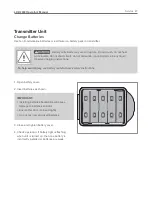
Page 48: ...se in any liquid Observe charging instructions To help avoid injury see battery manufacturer s safety instructions 1 Open battery cover 2 Insert batteries as shown IMPORTANT Installing batteries backw...

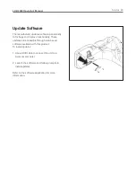
Page 49: ...ugs and improve functionality These updates are accessible through web based software available with this product To install updates 1 Use a USB cable to connect the unit to a personal computer 2 Laun...

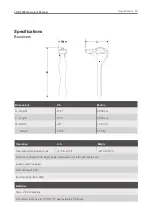
Page 50: ...idth 4 8 Weight 4 8 lb 12 19 cm 2 18 kg Operation U S Metric Operating temperature range 4 F to 122 F 20 C to 50 C Antenna configurations single peak twin peak null left right cable only Audio output...

Page 51: ...Battery saver unit shuts off after 5 minutes of inactivity...

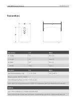
Page 52: ...ating temperature range 4 F to 122 F 20 C to 50 C Maximum power output 12 watts Standard operating frequency Over 70 frequencies Timer unit runs continuously or shuts off after running for a selected...

Page 53: ...finding signal is compatible with A Frame accessory Locating Ranges U S Metric Cables 15 4 6 m Beacons 10 3 m Depth Estimate Tolerances U S Metric Passive cable 10 0 5 10 0 15 3 m Active cable 5 0 2 1...

Page 54: ...LKZ 2000 Operator s Manual Specifications 52...

Page 55: ...rial number and approximate date of your equipment purchase This information should be recorded and placed on file by the owner at the time of purchase Return damaged unit to dealer for inspection and...

Page 56: ...tion by Manufacturer or authorized repair centers An inspection must occur within thirty 30 days of the date of failure of the product or part by Manufacturer or its authorized repair facility Manufac...

Page 57: ...andslides Weather conditions lightning strikes Defects at the production stage gas inclusions heterogeneity of the insulation IMPORTANT Although there are other types of damage this device is designed...

Page 58: ...ears Operation of the transmitter 1 Turn off the power supply and insulate the cable at both ends it cannot be grounded Disconnecting with the switch is generally insufficient to insulate the cable fo...

Page 59: ...the opposite side of the screen under a flap 3 When A frame is connected to the receiver the receiver automatically enters the fault mode A frame symbol is displayed and displays house symbol in the...

Page 60: ...take a step back and drive again A frame into the ground 3 Repeat step 2 moving on shorter distances until the arrow changes its direction after moving only by a few centimeters The location where th...

Reviews: