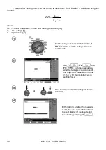
MIC-05s1
– USER MANUAL
21
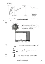
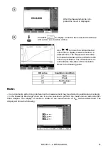
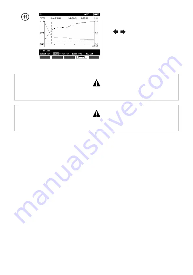
Result presented as a chart. Dashed hor-
izontal line shows the value of set limit.
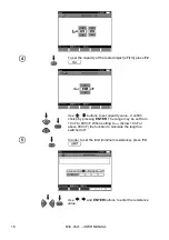
Use
,
to move the vertical dashed
cursor line to display measurements at a
selected time. The display will show data
for the cursor point showing the R
ISO
, I
L
and time.
Note:
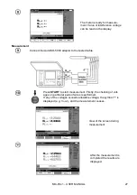
During measurements of insulation resistance dangerous voltages up to 10 kV occur at the
ends of the test leads of the meter.
Do not disconnect test leads before the measurement is completed. Failure to obey will lead
to high voltage electric shocks and make it impossible to discharge the tested object.
- Disabling t
2
will also disable t
3
.
- Measuring time t
n
is independent of the t
1
, t
2
, t
3
times set in MENU and overwrites these values. When
t
n
< t
3
then the measurement time will be equal to t
n
.
- Timer measuring the measurement time is started when V
ISO
voltage is stabilized.
-
LIMIT I
message means operation with limited power output. If this condition persists for 20 seconds
the measurement is interrupted.
- If any of the measured values of partial resistance is out of range the value of the absorption coefficient
is not displayed
– the display shows dashes.
- During the measurement the yellow
HV
LED is shining.
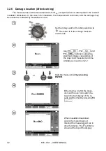
- After completion of a measurement the charge due to the capacitance of the object tested is discharged
by shorting
R
ISO
+
and
R
ISO
-
terminals with a resistance of 200 k
, simultaneously displaying displaying
the voltage of the tested object.
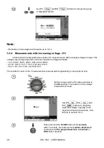
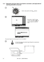
- For power cables measure the insulation resistance between each conductor and other conductors
shorted and grounded (figure below).
- The length of the cable is calculated from the value of capacity in [km] entered in the menu before the
measurement.


