background image

MIC-05s1 

– USER MANUAL 

58 

- Do not exceed the charging current, as it may result in ignition or "swelling" of the battery pack. "Swol-
len" battery pack must not be used. 
- Do not charge or use the batteries in extreme temperatures. Extreme temperatures reduce the lifetime 
of rechargeable batteries. Always observe the rated operating temperature. Do not dispose the battery 
pack into fire. 
- Li-Ion cells are sensitive to mechanical damage. This kind of damage may cause its permanent dam-
age and thus - ignition or explosion. Any interference in the structure of Li-ion battery pack may cause 
its damage. This may result in the ignition or explosion. A short-circuit of the battery poles "+" and "-" 
may permanently damage the battery pack or even cause its fire or explosion. 
- Do not immerse Li-Ion battery in liquids and do not store in humid conditions.  
 
- If the electrolyte contained in the Lithium-Ion battery pack, contacts eyes or skin, immediately rinse the 
affected place with plenty of water and consult a doctor. Protect the battery against unauthorised per-
sons and children. 
- When you notice any changes in the Lithium-Ion battery pack (e.g. changes in colour, swelling, exces-
sive temperature), stop using the battery pack. Li-Ion batteries that are mechanically damaged, over-
charged or excessively discharged are not suitable for use. 
- Any misuse of the battery may cause its permanent damage. This may result in the ignition. The seller 
and the manufacturer shall not be liable for any damages resulting from improper handling Li-Ion battery 
pack. 

Cleaning and maintenance 


ATTENTION! 

Use only the maintenance methods specified by the manufacturer in this manual.  


The casing of the meter may be cleaned with a soft, damp cloth using all-purpose detergents. Do 

not use any solvents or abrasives which might scratch the casing.  
 

Clean the probe with water and dry thoroughly. Before the probe is stored for a prolonged time it 

is recommended to grease it with any machine lubricant. 
 

The reels and test leads should be cleaned with water and detergents and dried. 


The electronic system of the meter does not require maintenance. 


Storage 

 
When storing the meter the following recommendations must be observed: 


Disconnect all the test leads from the meter. 


Clean the meter and all its accessories thoroughly. 


Wind the long test leads onto the reels. 


If meter is to be stored for a prolonged time remove the batteries from the meter. 


In order to prevent a total discharge of the batteries during storage charge them periodically. 


 Dismantling and utilisation 


Scrap, disused and spent electric / electronic equipment should be disposed of responsibly, i.e. it 

must not be placed with other types of waste. 
 

Scrap, disused and spent electric / electronic equipment should be sent to a collection point des-

inated for the disposal of waste electrical and electronic equipment. 
 

Before waste equipment is sent to a collection point do not dismantle or disassemble. 


Observe  local  regulations  concerning  the  disposal  of  waste  electronics,  batteries,  and  related 

components. 
 

Summary of Contents for MIC-05s1

Page 1: ......

Page 2: ......

Page 3: ...USER MANUAL INSULATION RESISTANCE METER MIC 05s1 SONEL TEST MEASUREMENT Santa Clara Ca 95051 USA SONEL S A widnica Poland Version 1 12 01 07 2020...

Page 4: ...onable protection against harmful interference when the equipment is operated in a commercial environment This equipment generates uses and can radiate radio frequency energy and if not installed and...

Page 5: ...ment of insulation resistance 16 3 2 1 Double lead measurement 17 3 2 2 Three lead measurement 22 3 2 3 Measurements with AutoISO 5000 25 3 2 4 Measurements with increasing voltage SV 28 3 2 5 Dielect...

Page 6: ...6 2 Battery power 56 6 3 Charging rechargeable battery 57 6 4 Power supply from mains 57 6 5 General principles for using Li Ion rechargeable batteries 57 7 Cleaning and maintenance 58 8 Storage 58 9...

Page 7: ...ts to avoid to the risk of electric shock The MIC 05s1 will discharge the electric charge at the end of the test automatically Using this manual does not exclude the need to comply with occupational h...

Page 8: ...ying Installation failed message Cause Windows 8 and Windows 10 by default blocks drivers without a digital signature Solution Disable the driver signature enforcement in Windows 2 Menu Press MENU but...

Page 9: ...t values Temperature unit Cell autoincrementing Filter restricting RISO display Chart type selection Use and buttons to select desired po sition Enter a selected option by pressing ENTER 2 2 1 Mains f...

Page 10: ...and press buttons to set time values Confirm your choice by pressing ENTER Selection ranges are t1 1 s to 600 s t2 1 s to 600 s but t1 t3 1 s to 600 s but t2 2 2 3 Type of absorption coefficients Use...

Page 11: ...rent value Confirm your choice by pressing ENTER 2 2 5 Setting limit values Use buttons to switch on off limit values Confirm your choice by pressing ENTER 2 2 6 Temperature unit Use to select the tem...

Page 12: ...igital filter for accurate results in difficult and unstable measurement conditions The meter displays a filtered value of measurements for a specified time pe riod which may be 10 s 30 s 60 s 100 s 2...

Page 13: ...R plots Use buttons to select the values to be displayed on the chart Confirm your cho ice by pressing ENTER 2 3 Meter Settings The options for Meter Settings consists of LCD contrast Automatic shut o...

Page 14: ...LCD contrast Select contrast value using and buttons Confirm choice by pressing ENTER 2 3 2 Automatic shut off Auto OFF Changing the shut off time of an idle meter Use buttons to set Auto OFF time Con...

Page 15: ...month year hour minute Set a required value using buttons When settings are finished press ENTER 2 3 4 Factory default settings In order to reset to factory default settings highlight YES using button...

Page 16: ...oad the latest version of firmware from the Downloads section at either web site www sonel pl or www soneltest com and save the file on your PC Connect the meter to PC Select Firmware upgrade in the M...

Page 17: ...MIC 05s1 USER MANUAL 15 2 4 Language choice Use buttons to select desired lan guage and press ENTER 2 5 Information about manufacturer...

Page 18: ...quipotential bonding it is the maximum value The limits are programmed in the main menu Section 2 1 5 When setting of limits is activated the display will show in the lower left corner the following s...

Page 19: ...ction selection switch at the position of a chosen RISO measuring voltage The voltage is adjusted as follows 50 V to1 kV in 10V steps 1 kV to 5 kV in 25V steps The meter measures the interference volt...

Page 20: ...et capacity value Confirm choice by pressing ENTER The range may be set from 10 nF to 990 nF When setting to below 10 nF or above 990 nF the function to calculate the length is switched off In order t...

Page 21: ...the limit value is from 1 k to 40 T The meter is ready for measure ment Value of interference voltage can be read on the display Connect test leads according to the following diagram Press and hold th...

Page 22: ...ment will be stopped when the programmed time is reached or the ESC button pressed View of the screen during meas urement Press F4 to display a chart of the measured resistance and current as a functi...

Page 23: ...asurement time will be equal to tn Timer measuring the measurement time is started when VISO voltage is stabilized LIMIT I message means operation with limited power output If this condition persists...

Page 24: ...1500V for AC two tone beep The tested object is live The measurement is blocked LIMIT I Current limit exceeded The symbol displayed is accompa nied by a continuous beep HILE Leakage current too high b...

Page 25: ...one of the windings and the transformer s enclosure connect the G socket of the meter to the second winding as follows When measuring insulation resistance between one of the cable conductors and the...

Page 26: ...conductors of the cable attach ing the foil to the G terminal to ignore other conductors that do not take part in the measurement For the measurement of insulation resistance of a high voltage circui...

Page 27: ...rance Use F1 F2 and F3 buttons to adjust the desired test voltage the capacity of the object and the measurement time Similarly as in section 3 2 2 Press F4 button to enter the selection of lead ca bl...

Page 28: ...MANUAL 26 Press F4 to set the minimum resistance It is the same for all conductor pairs of a cable Use and ENTER buttons to enter the resistance value Use and ENTER buttons to select the unit Confirm...

Page 29: ...000 adapter to the tested cable Press START to start measurement Firstly the checking of volt ages on particular pairs of wires is performed If any of the voltages exceeds allowable voltage the symbol...

Page 30: ...1000 V 2 5 kV 500 V 1 kV 1 5 kV 2 kV and 2 5 kV 5 kV 1 kV 2 kV 3 kV 4 kV and 5 kV The results for each of the 5 measurements is saved and is signalled by a beep and an icon Set the rotary switch of fu...

Page 31: ...lowing 3 2 5 Dielectric Discharge Indicator DD In the dielectric discharge test the discharge current is measured after 60 seconds from the end of measurement when charging of the insulation is comple...

Page 32: ...citance F Set the rotary function selection switch at DD The meter is in the voltage measure ment mode Use F1 F2 and F3 buttons to adjust de sired test voltage capacitance of the object and measuremen...

Page 33: ...where the cursor is positioned The measurement re sult indicates the status of the insulation Refer to the following table DD value Insulation condition 7 Bad 4 7 Weak 2 4 Not the best 2 OK Note In en...

Page 34: ...function selection at The meter is in the voltage measure ment mode Use F1 F2 and F3 buttons to adjust de sired test voltage capacitance of the object and measurement time similarly as in section 3 2...

Page 35: ...display a chart of the measured resistance and current as a function of time 3 3 Low voltage measurement of resistance Note Low voltage measurement of resistance RCONT is supported only in meters wit...

Page 36: ...tential bonding with 200 mA current Set the rotary switch at the RCONT position The meter is ready for meas urement Press F4 to set the maximum resistance value The value may be set in the range from...

Page 37: ...uncer tainty that is specified in the technical data Voltage on object Un 10 V two tone continuous beep and LED lit in red Interference voltage exceeds the allowable value the measurement ceases 3 3...

Page 38: ...fault calibration perform the above step with test leads not connected together 3 4 Temperature measurement To include temperature measurements for each test function simply connect the temperature pr...

Page 39: ...ked at 1 metre intervals with the following data name of the manufacturer cable type rated voltage number of conductors and cross sec tion of each of them For example the photograph shows a ca ble of...

Page 40: ...he length is switched off Press ENTER to confirm the selection Start the measurement The device measures the total capacity of the cable C nF Using this value and when the unit capacity CX nF km is en...

Page 41: ...ed for these objects Addi tionally the memory has a space for the list of names selection lists extended up to 99 entries 4 1 1 The appearance of main windows in the measurement recording mode The mai...

Page 42: ...b object Sub object containing more sub objects Sub object symbol on a grey back ground Connector appears when the cursor is over the icon Client edit window Active field Data fields Window for enteri...

Page 43: ...ment settings date and time of the measurement are stored in the memory Cells unsaved are not available It is recommended to delete the memory after reading the data or before performing a new series...

Page 44: ...the result in the memory or ESC to return to displaying the memory structure If you try to store data in an occupied memory cell the following warning message will appear or After selecting YES press...

Page 45: ...1 USER MANUAL 43 4 2 2 Extending the memory structure Press ESC to start creating the objects Press button to set the cursor on Client 1 Use buttons to select other clients 1 10 Press F1 to edit clien...

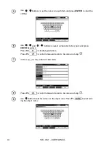
Page 46: ...character to be typed and press ENTER to enter it Press F4 to delete typed letters Press F5 to confirm data and return to the screen of step In this way you may enter all client data Press F5 to confi...

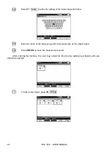
Page 47: ...use the list of proposed names that is available after pressing F1 First the list should be created After pressing F1 you may add further names to the list up to 99 items and pressing F2 deletes the...

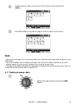
Page 48: ...ing point name Enter the name of the measuring point in the same way as the object name Press ENTER to save the measurement result After entering the memory the user may extend its structure by adding...

Page 49: ...the object marked with the cursor sub object The screen displays only sub objects belonging to the object sub object indicated by the cursor Deleting objects and sub objects is possible only in memory...

Page 50: ...ns to move between objects and sub objects using the existing connectors Press F1 to enter the option for editing the name of object sub ob ject and change it Press F2 to delete a chosen object sub ob...

Page 51: ...t Use buttons to change the measurement point Press F1 to enter the editing of the measuring point name and to change it Press F4 or F5 to display all individual types of results for a given point Pre...

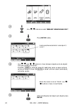
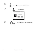
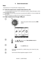
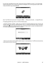
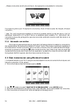
Page 52: ...MIC 05s1 USER MANUAL 50 Use buttons to select MEMORY ERASING Press ENTER button Use buttons to select YES or NO Press ENTER button...

Page 53: ...software may be used for many devices manufactured by SONEL S A that are equipped with the USB interface Detailed information is available from the manufacturer and distributors 5 2 Data transmission...

Page 54: ...t in pairing mode via a special button on the keyboard please refer to the manual of the keyboard Select F1 Search on the meter The meter will search for available Bluetooth devices the time to find B...

Page 55: ...de The pairing operation may end in one of three following ways Wireless connection enabled pairing was successful the keyboard pairing has been saved in the memory and will not require re entering th...

Page 56: ...d in connect mode This process is automatic regardless of the measurement function except the case of an active connection to a PC via Bluetooth and charger Automatic connection is indicated by symbol...

Page 57: ...roceed in accordance with its instructions 5 5 Read out and change of PIN code for Bluetooth connections Select Wireless transmission in the main MENU of the meter press ENTER Select CHANGE PIN CODE p...

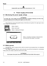
Page 58: ...ol in the right upper corner of the display on a current basis Battery charged Battery discharged Battery completely discharged Battery completely discharged Measurements cannot proceed until battery...

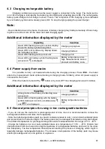
Page 59: ...hile remaining in charging mode Similarly when AC power supply is connected to the meter When the meter is turned off by button or by Auto OFF the charging process will continue Additional information...

Page 60: ...er and the manufacturer shall not be liable for any damages resulting from improper handling Li Ion battery pack 7 Cleaning and maintenance ATTENTION Use only the maintenance methods specified by the...

Page 61: ...to 20 0T Measurement with DC and increasing voltage SV for UISO 5 kV Display range Resolution Basic uncertainty 000 k to 999 k 1 k 3 m v 10 digits 1 00 M to 9 99 M 0 01 M 10 0 M to 99 9 M 0 1 M 100 M...

Page 62: ...act of G terminal 0 05 with reduced current leakage incurred by 250 k resistance during 100 M measurement with 50 V measurement voltage Max short circuit current 6 mA 15 Measuring charging current in...

Page 63: ...tion of test leads resistance autozeroing Temperature Measurement Display range Resolution Basic uncertainty 40 0 to 99 9 C 0 1 C 3 m v 8 digits 40 0 to 211 8 F 0 1 F 3 m v 16 digits Other technical d...

Page 64: ...6 10 2 2 Additional uncertainties according to EN 61557 4 RCONT Significant parameter Designation Additional uncertainty Position E1 0 Supply voltage E2 0 2 BAT is not lit Temperature 32 F to 95 F 0 C...

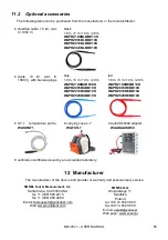
Page 65: ...1 8 m 5 m 10 m 20 m WAPRZ1X8REBB10K WAPRZ005REBB10K WAPRZ010REBB10K WAPRZ020REBB10K ST 1 temperature probe WASONT1 carrying case L 7 WAFUTL7 AutoISO 5000 adapter WAADAAISO50 calibration certificate is...

Page 66: ...rs o luxmeters The Calibration Certificate is a document that presents a relation between the calibration standard of known accuracy and meter indications with associated measurement uncertainties The...

Page 67: ......

Page 68: ......

Reviews: