OPERATING MANUAL MIC-10s1 version 1.03
16
3
Measurements
Notes:
The results of the last measurement are stored by the meter until the next measurement is started
or the measuring function is changed by means of the rotary switch. The result of the latest measure-
ment is displayed on the screen for 20 seconds. It may be recalled by pressing
ENTER
, or after the
meter is turned off and turned back on again.
WARNING:
During a measurement do not change the rotary switch because it may damage the meter
and pose a threat to the user.
3.1 Diagnostics performed by the meter - limits
The meter is able to assess whether the measurement result is within acceptable limits. The user
may set limits, i.e. maximum or minimum values, which should not be exceeded. For measurements of
insulation resistance the set limit is the minimum value, whereas for measurements of continuity of pro-
tective conductors and equipotential bonding it is the maximum value.
The limits are programmed in the main menu (Section 2.1.5). When setting of limits is activated
the display will show in the lower left corner the following symbols:
-
: the result is correct; i.e. within the set limits
-
: the result is incorrect; i.e. is outside the set limits
The method for setting limits is described in the chapter 3.2.1. In DD, SV functions and in after-
burning - it is not possible to set limits.
3.2 Measurement of insulation resistance
WARNING:
The tested object must not be live.
Note:
During measurement, especially of high resistances, make sure that test leads or probe croc-
odile clips do not touch each other. Such a contact may cause the flow of surface currents
resulting in additional error in measurement results.
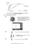
The meter’s current generation output is limited at 1.2 mA, 3 mA or 5 mA level. Exceeding the
current limit is indicated by a continuous beep. The test result will still be correct. Note that the test
voltage at the test terminals is lower than the test voltage the user selected before commencing the
measurement. The current limitation occurs in the first phase of the measurement due to charging the
capacity of the tested object.
Summary of Contents for MIC-10s1
Page 1: ......
Page 2: ......
Page 3: ......
Page 4: ......
Page 19: ...OPERATING MANUAL MIC 10s1 version 1 03 15 2 5 Information about manufacturer...
Page 69: ...OPERATING MANUAL MIC 10s1 version 1 03 65...
Page 70: ...OPERATING MANUAL MIC 10s1 version 1 03 66...
Page 71: ......
Page 72: ......


