background image

OPERATING MANUAL MIC-10s1 version 1.03 

47 


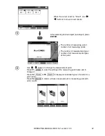
When the cursor is set on "Client", use 

 buttons to move to next clients. 


After selecting desired object (sub-object) press 

ENTER


The number of measuring point / 
number of all measuring points. 
 
The number of measurement type / 
number of all measurements types 
at that point. 


Use 

 buttons to change the measurement point. 

Press 

F1 

 to enter the editing of the measuring point name and to 

change it.  
Press 

F4 

 or 

F5 

 to display all individual types of results for a 

given point. 
Press 

F2 

 to delete a chosen measurement or measuring point with 

all its results: 


Summary of Contents for MIC-10s1

Page 1: ......

Page 2: ......

Page 3: ......

Page 4: ......

Page 5: ...OPERATING MANUAL INSULATION RESISTANCE METER MIC 10s1 SONEL TEST MEASUREMENT Santa Clara Ca 95051 USA SONEL SA widnica Poland Version 1 03...

Page 6: ...vide reasonable protection against harmful interference when the equipment is operated in a commercial environment This equipment generates uses and can radiate radio frequency energy and if not insta...

Page 7: ...3 5 Firmware update 13 2 3 6 Button Sounds 13 2 3 7 Wireless communication 14 2 4 LANGUAGE CHOICE 14 2 5 INFORMATION ABOUT MANUFACTURER 15 3 MEASUREMENTS 16 3 1 DIAGNOSTICS PERFORMED BY THE METER LIM...

Page 8: ...omatic connection 52 5 4 DATA TRANSMISSION USING BLUETOOTH MODULE 52 5 5 READ OUT AND CHANGE OF PIN CODE FOR BLUETOOTH CONNECTIONS 53 6 POWER SUPPLY OF THE METER 55 6 1 MONITORING THE POWER SUPPLY VOL...

Page 9: ...measurements to avoid to the risk of electric shock The MIC 10s1 will discharge the electric charge at the end of the test automatically Using this manual does not exclude the need to comply with occu...

Page 10: ...in displaying Installation failed message Cause Windows 8 and Windows 10 by default blocks drivers without a digital signature Solution Disable the driver signature enforcement in Windows 2 Menu Press...

Page 11: ...mit values Temperature and distance units Cell autoincrementing Filter restricting RISO display Chart type selection Use and buttons to select desired po sition Enter a selected option by pressing ENT...

Page 12: ...tween times and buttons to set time values Con firm your choice by pressing ENTER Selection ranges are t1 1 s to 600 s t2 1 s to 600 s but t1 t3 1 s to 600 s but t2 2 2 3 Type of absorption coefficien...

Page 13: ...choice by pressing ENTER 2 2 5 Setting limit values Use buttons to switch on off limit val ues Confirm your choice by pressing ENTER 2 2 6 Temperature and distance units Use buttons to scroll between...

Page 14: ...onditions The meter displays a filtered value of measurements for a specified time pe riod which may be 10 s 30 s 60 s 100 s 200 s or after selecting the SMART option enables the filter which effectiv...

Page 15: ...firm your cho ice by pressing ENTER 2 3 Meter Settings The options for Meter Settings consists of LCD contrast Automatic shut off Date and time Factory default settings Firmware update Button sounds W...

Page 16: ...CD contrast Select contrast value using and buttons Confirm choice by pressing ENTER 2 3 2 Automatic shut off Auto OFF Changing the shut off time of an idle meter Use buttons to set Auto OFF time Conf...

Page 17: ...ware update ATTENTION Before updating the meter s firmware first charge the battery During the update the meter must not be switched off and the communications cable to the PC must not be disconnected...

Page 18: ...itch on off button sounds Confirm your choice by pressing ENTER 2 3 7 Wireless communication Use buttons to switch on off wireless communication Confirm your choice by pressing ENTER 2 4 Language choi...

Page 19: ...OPERATING MANUAL MIC 10s1 version 1 03 15 2 5 Information about manufacturer...

Page 20: ...ts are programmed in the main menu Section 2 1 5 When setting of limits is activated the display will show in the lower left corner the following symbols the result is correct i e within the set limit...

Page 21: ...tary function selection switch at the position of a chosen RISO measuring voltage The voltage is adjusted as follows 50 V to1 kV in 10V steps 1 kV to 10 kV in 25V steps The meter measures the interfer...

Page 22: ...tons to set capacity value Confirm choice by pressing ENTER The range may be set from 10 nF to 990 nF When setting to below 10 nF or above 990 nF the function to calculate the length is switched off I...

Page 23: ...lue The range of setting the limit value is from 1 k to 40 T The meter is ready for measure ment Value of interference voltage can be read on the display Connect test leads according to the following...

Page 24: ...en release the buttons To interrupt the measurement in this mode press START again or press ESC View of the screen during meas urement Press F4 to display a chart of the measured resistance and curren...

Page 25: ...en the measurement time will be equal to tn Timer measuring the measurement time is started when VISO voltage is stabilized LIMIT I message means operation with limited power output If this condition...

Page 26: ...V 50V V 1500V for AC two tone beep The tested object is live The measurement is blocked LIMIT I Current limit exceeded The symbol displayed is accompa nied by a continuous beep HILE Leakage current t...

Page 27: ...e between one of the windings and the transformer s enclosure connect the G socket of the meter to the second winding as follows When measuring insulation resistance between one of the cable conductor...

Page 28: ...tween two conductors of the cable attach ing the foil to the G terminal to ignore other conductors that do not take part in the measurement For the measurement of insulation resistance of a high volta...

Page 29: ...n ap pearance Use F1 F2 and F3 buttons to adjust the desired test voltage the capacity of the object and the measurement time Similarly as in section 3 2 2 Press F4 button to enter the selection of le...

Page 30: ...s1 version 1 03 26 Press F4 to set the minimum resistance It is the same for all conductor pairs of a cable Use and ENTER buttons to enter the resistance value Use and ENTER buttons to select the unit...

Page 31: ...AutoISO 5000 adapter to the tested cable Press START to start measurement Firstly the checking of volt ages on particular pairs of wires is performed If any of the voltages exceeds allowable voltage t...

Page 32: ...00 V and 1000 V 2 5 kV 500 V 1 kV 1 5 kV 2 kV and 2 5 kV 5 kV 1 kV 2 kV 3 kV 4 kV and 5 kV 10kV 2 kV 4 kV 6 kV 8 kV 10 kV The results for each of the 5 measurements is saved and is signalled by a beep...

Page 33: ...show the following 3 2 5 Dielectric Discharge Indicator DD In the dielectric discharge test the discharge current is measured after 60 seconds from the end of measurement when charging of the insulat...

Page 34: ...V C capacitance F Set the rotary function selection switch at DD The meter is in the voltage measure ment mode Use F1 F2 and F3 buttons to adjust de sired test voltage capacitance of the object and m...

Page 35: ...he point where the cursor is positioned The measurement re sult indicates the status of the insulation Refer to the following table DD value Insulation condition 7 Bad 4 7 Weak 2 4 Not the best 2 OK N...

Page 36: ...witch of function selection at The meter is in the voltage measure ment mode Use F1 F2 and F3 buttons to adjust de sired test voltage capacitance of the object and measurement time similarly as in sec...

Page 37: ...ess F4 to display a chart of the measured resistance and current as a function of time 3 3 Low voltage measurement of resistance 3 3 1 Measurement of resistance of protective conductors and equipotent...

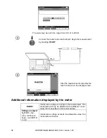
Page 38: ...mpletes the result is shown on the display screen Additional information displayed by the meter NOISE Interference voltage occurring on the tested object The measurement may be affected with additiona...

Page 39: ...ctions displayed on the screen Press START An AUTOZERO message appears Confirming that calibration of the test leads has been performed The meter then enters the measurement mode The AUTOZERO message...

Page 40: ...display indicates the measured temperature along with the measurement results If the tem perature probe is not connected the display shows T Values are refreshed every second To ensure user safety it...

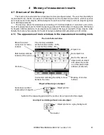
Page 41: ...out created for these objects Addi tionally the memory has a space for the list of names selection lists extended up to 99 entries 4 1 1 The appearance of main windows in the measurement recording mod...

Page 42: ...r this sub object Sub object containing more sub objects Sub object symbol on a grey back ground Connector appears when the cursor is over the icon Client edit window Active field Data fields Window f...

Page 43: ...t measurement settings date and time of the measurement are stored in the memory Cells unsaved are not available It is recommended to delete the memory after reading the data or before performing a ne...

Page 44: ...R to save the result in the memory or ESC to return to displaying the memory structure If you try to store data in an occupied memory cell the following warning message will appear or After selecting...

Page 45: ...MIC 10s1 version 1 03 41 4 2 2 Extending the memory structure Press ESC to start creating the objects Press button to set the cursor on Client 1 Use buttons to select other clients 1 10 Press F1 to e...

Page 46: ...select a character to be typed and press ENTER to enter it Press F4 to delete typed letters Press F5 to confirm data and return to the screen of step In this way you may enter all client data Press F5...

Page 47: ...a You may use the list of proposed names that is available after pressing F1 First the list should be created After pressing F1 you may add further names to the list up to 99 items and pressing F2 del...

Page 48: ...he measuring point name Enter the name of the measuring point in the same way as the object name Press ENTER to save the measurement result After entering the memory the user may extend its structure...

Page 49: ...objects in a level are added on the right side of the object marked with the cursor sub object The screen displays only sub objects belonging to the object sub object indicated by the cursor Deleting...

Page 50: ...to select MEMORY BROWSE AND EDIT Press ENTER button Last saved measurement in sub object 3 Level 1 Use and buttons to move between objects and sub objects using the existing connectors Press F1 to ent...

Page 51: ...point number of all measuring points The number of measurement type number of all measurements types at that point Use buttons to change the measurement point Press F1 to enter the editing of the meas...

Page 52: ...MIC 10s1 version 1 03 48 4 4 Deleting memory data Set the rotary switch of function selection at MEM position Use buttons to select MEMORY ERASING Press ENTER button Use buttons to select YES or NO Pr...

Page 53: ...e meter The software may be used for many devices manufactured by SONEL S A that are equipped with the USB interface Detailed information is available from the manufacturer and distributors 5 2 Data t...

Page 54: ...Search on the meter The meter will search for available Bluetooth devices the time to find Bluetooth devices depends on the number of available devices within range After completing the search proces...

Page 55: ...in the memory and will not require re entering the PIN even if you change the PIN of the meter Connection is indicated by symbol displayed near the clock and it may be seen on the list of available de...

Page 56: ...utomatic regardless of the measurement function except the case of an active connection to a PC via Bluetooth and charger Automatic connection is indicated by symbol located near the clock When more t...

Page 57: ...PE and proceed in accordance with its instructions 5 5 Read out and change of PIN code for Bluetooth connections Select Wireless transmission in the main MENU of the meter press ENTER Select CHANGE P...

Page 58: ...OPERATING MANUAL MIC 10s1 version 1 03 54 Note Standard PIN code for Bluetooth transmission is 123...

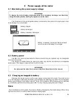
Page 59: ...gnated Sonel servicing center The charger is installed inside the meter and works only with the manufacturer s rechargeable battery pack The charger is powered from the 230 V mains ATTENTION Do not po...

Page 60: ...he ambient temperature for prolonged storage should be maintained within the range of 5 C 25 C Charge the batteries in a cool well ventilated place at a temperature of 10 C 28 C Modern fast chargers d...

Page 61: ...grease it with any machine lubricant The reels and test leads should be cleaned with water and detergents and dried The electronic system of the meter does not require maintenance 8 Storage When stori...

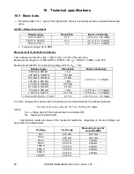
Page 62: ...solution Basic uncertainty 000 k to 999 k 1 k 3 m v 10 digits 1 00 M to 9 99 M 0 01 M 10 0 M to 99 9 M 0 1 M 100 M to 999 M 1 M 1 00 G to 9 99 G 0 01 G 10 0 G to 99 9 G 0 1 G 100 G to 999 G 1 G 3 5 m...

Page 63: ...M to 9 99 M 0 01 M 10 0 M to 99 9 M 0 1 M 100 M to 999 M 1 M 1 00 G to 9 99 G 0 01 G 10 0 G to 99 9 G 0 1 G 100 G and above to the value at which the addi tional uncertainty of Au toISO 5000 is 5 1 G...

Page 64: ...losed enclosure d power supply of the meter 14 8 V 5 3 Ah Li Ion battery 90 V 260 V 50 Hz 60 Hz e dimensions 15 4 in x 12 2 in x 6 3 in 390 mm x 310 mm x 180 mm f meter weight approx 12 3 lbs 5 6 kg g...

Page 65: ...tion 10 2 1 Additional uncertainties according to EN 61557 2 RISO Significant parameter Designation Additional uncertainty Position E1 0 Supply voltage E2 1 BAT is not lit Temperature 32 F to 95 F 0 C...

Page 66: ...V 3 pcs black red and blue pin probe 11 kV DC with banana socket 2 pcs red and black temperature probe ST 1 USB cable power supply 230 V cable case L 4 for accessories operating manual calibration cer...

Page 67: ...kV cat IV 1000V 10 m cable 10 kV red cat IV 1000V with banana plugs 10 m cable blue 10 kV cat IV 1000V terminated with banana plugs AutoISO 5000 adapter 20 m cable blue 10 kV cat IV 1000V terminated w...

Page 68: ...ovider of warranty and post warranty service SONEL Test Measurement Inc Santa Clara Ca 95054 USA tel 1 408 988 1346 fax 1 408 988 4869 E mail office soneltest com Web www soneltest com SONEL S A widni...

Page 69: ...OPERATING MANUAL MIC 10s1 version 1 03 65...

Page 70: ...OPERATING MANUAL MIC 10s1 version 1 03 66...

Page 71: ......

Page 72: ......

Reviews: