OPERATING MANUAL MIC-2501 version 1.04
12
Use
and
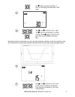
to see individual components of the
result in the following order:
R
ISO
→I
L
→Ab2→Ab1→Rt3→It3→Rt2→It2→Rt1→It1
→R
ISO
.
If the measurement is stopped, the displayed val-
ues will present the results of partial measurements
that have been completed and "---" will represent
uncompleted partial measurements.
If the characteristic was measured, then the meas-
urement results may be read between It1 and R
ISO
.
Note:
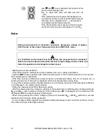
During measurements of insulation resistance, dangerous voltage of approx.
2.5kV occurs at the ends of measurement wires of MIC-2501 meter.
It is forbidden to disconnect test leads before the measurement is completed.
Failure to obey the above instruction will lead to high voltage electric shock and
make it impossible to discharge the tested object.
- Disabling t2 will also disable t3.
- Timer measuring the measurement time is started when U
ISO
voltage is stabilized.
- Symbol
LIMIT
means operation with limited inverter power. If this condition persists for 20 seconds,
the measurement is interrupted.
- If the timer reaches characteristic points (tx times or characteristic times), then for 1s instead U
ISO
a
symbol (mnemonic) of this point is displayed which is accompanied by a long beep.
- If any of the measured values of partial resistance is out of range, the value of the absorption coefficient
is not displayed
– the display shows dashes.
- During the measurement LED is flashing in yellow.
- When the measurement is complete, capacity of the tested object is discharged by shorting terminals
R
ISO
+
and
R
ISO
-
with resistance of approx. 100 k
. Message „
diS
” is displayed. Do not disconnect the
test leads before the object capacity id discharged.
- When during viewing the results, voltage is present at terminals
R
ISO
, LED
R
ISO
will blink in red and
additional two-tone beep will be generated.
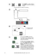
- In case of power cables measure the insulation resistance between each conductor and other conduc-
tors shorted and grounded (figure below).


