background image

OPERATING MANUAL MIC-2501 version 1.04 

25 

Power supply 

8.1  Monitoring the power supply voltage 

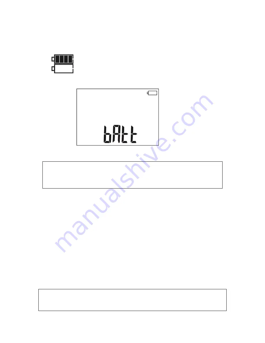
The charge level of the battery pack is indicated by the symbol in the right upper corner of the display 

on a current basis: 


The battery pack is charged. 


The charge of battery pack is low. Only voltage measurement is 
available. 


No  battery  icon  (when  the  charger  is  connected).  The  battery 
pack is disconnected or damaged. 


The battery pack is fully dis-
charged, all measurements are 
blocked. 
The  meter  switches  off  automati-
cally after 5 sec. 

8.2  Charging the battery pack 


CAUTION! 

MIC-2501 meter is powered from SONEL battery pack, which includes NiMH 9.6 
V batteries and it may be replaced only by the manufacturer's service department.  


Battery charger is installed inside the meter and 

cooperates only with the manufacturer’s recharge-

able battery pack. The charger is powered by external power supply adapter. The device may be also 
powered from the car cigarette lighter socket (

12V only

), using an optional charger.  

Charging commences once the power supply has been connected to the meter regardless of the 

fact whether the meter is on or off (only the charging mode is different - as described below). When the 
meter is switched off - the charging process is indicated on the screen by displaying animated symbol 
of battery being charged; when the meter is switched off - the charging is indicated by blinking LED's of 
measurement functions (they blink consecutively in red).  
Charging modes:  
- the meter (user interface) is switched off: the battery pack is charged in "quick charging" mode - the 
charging process takes approx. 4 hours. Completed charging is indicated by full battery symbol, 

FULL


message and beep. In order to fully turn the device off, unplug the power charger. 
- the meter (user interface) is switched on: the battery pack is charged in "background charging" mode 
- the charging may be longer than the charging process of the device which is switched off. Completed 
charging is indicated by full battery symbol and beep.  If the charging time exceeds 10 hours, the meter 
will automatically switch off for safety reasons. 

In order to fully turn the device off, unplug the power charger and turn the meter off. 


CAUTION! 

Do not power the meter from sources other than those listed in this manual. 


Summary of Contents for MIC-2501

Page 1: ......

Page 2: ......

Page 3: ...OPERATING MANUAL INSULATION RESISTANCE METER MIC 2501 SONEL S A ul Wokulskiego 11 58 100 widnica Poland Version 1 04 24 02 2017...

Page 4: ...version 1 04 2 MIC 2501 meter is a modern high quality easy to use and safe measuring device Please acquaint yourself with this manual in order to avoid measuring errors and prevent possible problems...

Page 5: ...NG THE MEASUREMENT RESULTS IN THE MEMORY 18 5 2 VIEWING MEMORY DATA 20 5 3 DELETING MEMORY DATA 21 5 3 1 Deleting bank data 21 5 3 2 Deleting the whole memory 22 6 DATA TRANSMISSION 24 6 1 COMPUTER CO...

Page 6: ...OPERATING MANUAL MIC 2501 version 1 04 4 13 ACCESSORIES 30 13 1 STANDARD EQUIPMENT 30 13 2 OPTIONAL ACCESSORIES 30 14 MANUFACTURER 31 15 LABORATORY SERVICES 32...

Page 7: ...and safety regula tions and with other relevant fire regulations required during the performance of a particular type of work Before starting the work with the device in special environments e g poten...

Page 8: ...tton for approx 2 sec Emer gency si tuations Pressing button for approx 7 sec onds will turn off the meter in case of emergency 3 Meter Configuration Turn on the meter by pressing and keeping SETUP bu...

Page 9: ...and buttons to turn the audio messages ON or OFF Press and buttons to enter the set ting the type of absorption coefficients FAC Use and buttons to set Ab1 Ab2 parameters or PI DAR Use and buttons to...

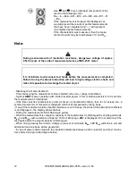
Page 10: ...tention During measurement especially of high resistances make sure that test leads do not touch each other and probes crocodile clips because such a contact may cause the flow of surface currents res...

Page 11: ...t3 value Press again to enter the set ting of time interval ChA of recording RISO Defining ChA interval will enable the user using Sonel Reader software to plot the resistance chart and current chart...

Page 12: ...rformed continu ously until you release the button or the pre set time is reached for 5 sec or In order to maintain hold the measure ment press and hold START button for 5 sec or press ENTER while hol...

Page 13: ...ENTER button or by press ing and holding START but ton for approx 5 sec Use SET SEL to go to display leakage cur rent IL After the measurement is completed or stopped read the result The re sults of...

Page 14: ...d when UISO voltage is stabilized Symbol LIMIT means operation with limited inverter power If this condition persists for 20 seconds the measurement is interrupted If the timer reaches characteristic...

Page 15: ...by a continuous beep Breakdown of the tested object insulation the measurement is in terrupted The message appears after displaying LIMIT I for 20 s during the measurement when the voltage previously...

Page 16: ...difficult weather conditions is eliminated by con necting a piece of metal foil insulating the tested conductor with G socket of the meter The same shall apply when measuring the resistance between tw...

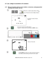
Page 17: ...0 mA current Use or button to start the measurement of RCONT LED is on The meter is in the voltage measure ment mode The meter is ready for meas urement Connect the meter to the tested object Trigger...

Page 18: ...compensation auto zeroing of resistance may be performed In RCONT mode LED is on use SET SEL button to en ter the screen with Autozeroing the test leads Short the test leads message READY will be disp...

Page 19: ...formed in a continu ous manner Additional information displayed by the meter 750V LED is blinking in red two tone acoustic signal is generated Measuring range is exceeded Voltage is higher than accept...

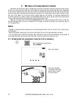
Page 20: ...ments in any chosen sequence and repeat them without losing other data Memory of measurement results is not deleted when the meter is switched off Thanks to this the data can be later read or sent to...

Page 21: ...ge the cell number or bank number When the cell number is flashing use and buttons to set the desired number of the cell Press SET SEL button bank number is flash ing Use and buttons to set the desire...

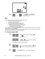
Page 22: ...an entry into the memory is introduced After exiting to the voltmeter by pressing ESC or after saving the results to the memory the last result may be recalled by pressing ENTER Complete set of resul...

Page 23: ...ess ESC to immediately display basic component of the result For RCONT there is no option of scrolling through the components of the result 5 3 Deleting memory data You can delete the entire memory or...

Page 24: ...e tion or Press ENTER button again to delete the selected bank After deleting the bank the meter beeps three times Cancel by pressing ESC The contents of the bank has been deleted 5 3 2 Deleting the w...

Page 25: ...symbol will be dis played to indicate the readiness for deleting the whole memory Press ENTER button and sym bols appear asking you to confirm dele tion or Press ENTER again After deleting the memory...

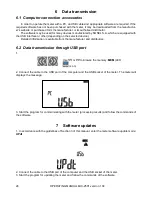
Page 26: ...n the selected device Detailed information is available from the manufacturer and distributors 6 2 Data transmission through USB port 1 Use or to browse the memory MEM LED is on 2 Connect the cable to...

Page 27: ...power supply has been connected to the meter regardless of the fact whether the meter is on or off only the charging mode is different as described below When the meter is switched off the charging p...

Page 28: ...emical processes may reduce their lifetime Rechargeable batteries NiMH usually lasts for 500 1000 charging cycles The rechargeable batteries reach their maximum capacity after being formatted 2 3 char...

Page 29: ...n the probe with water and dry it Before the probe is stored for a prolonged period of time it is recommended to grease it with any machine lubricant The reels and test leads should be cleaned with wa...

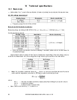
Page 30: ...G 99 99 G 0 01 G 100 0 G 999 9 G 0 1 G 1000 G 1 G When the range is exceeded the device displays xxxxG where xxxx is the limit value for the selected range Approximate maximum values of the measured...

Page 31: ...c to EN 61010 1 c degree of housing protection acc to EN 60529 IP65 d power supply of the meter SONEL battery pack NiMH 9 6 V 2 Ah e Battery charging time usually 4 h max 10 h f parameters of the exte...

Page 32: ...ended with banana plugs black cat IV 1 kV WAPRZ1X8BLBB 1 8 m 5 kV wire ended with banana plugs red cat IV 1 kV WAPRZ1X8REBB 1 8 m 5 kV wire ended with banana plugs blue cat IV 1 kV WAPRZ1X8BUBB croco...

Page 33: ...ble for charging the battery pack from the car cigarette lighter socket 12V WAADACS1 cable simulator CS 1 LSWPLMIC2501 calibration certificate Note The software is supported by the following systems W...

Page 34: ...ng compliance of parameters declared by the manufacturer of tested device with national standards specifying the measurement un certainty Pursuant to standard EN ISO 10012 2003 Measurement management...

Page 35: ......

Page 36: ......

Reviews: