OPERATING MANUAL MMR-630 Revision 1.6
20
Notes:
- In the automatic mode, the measurement is triggered once all the test leads have been connected to
the object. In order to start another measurement, it is sufficient to disconnect and then connect one
of the leads anew.
- Pay attention to the appropriate selection of the measurement terminals, since the precision of the
performed measurements depends upon the quality of the realised connections. They must provide
good contact and permit uninterrupted flow of the measurement current. It is unacceptable, for exam-
ple, to connect a crocodile clip on tarnished or rusty elements
– they must be previously cleaned or a
test prod must be used for measurements.
- In the case of measurements of inductive objects, select an inductive object. Should a resistance-
type object, the result may be burdened with significant errors or the measurement may be precluded.
- The declared value is valid for measurements of objects whose inductivity is up to 40H. It is also
possible to perform measurements for objects of a higher inductivity, but the result might be overstat-
ed.
- During measurements of objects of a high resistance and a very high inductivity at the current range
of 0.1mA it may not be possible to stabilise the result. In such a case the meter will display the result
with a one-grade-down resolution.
- If the value of the measured resistance is within the limit of subranges, it may happen that the value
measured for single-direction current is within the lower subrange (for resistance), and the value
measured for the opposite direction current is within the higher subrange. Then the principal result is
displayed with resolution that corresponds to the higher subrange (for resistance) and the value cor-
responding to that subrange is displayed as the measurement current.
-
In the case of manual selection of the measurement range the message „Unstable conditions!” may
mean the selected measurement current is too high. This is also sig
nalled by the symbol „OFL”, which
is displayed once the measurement has concluded.
NOTE!
Measurement leads must not be disconnected from the object during its discharg-
ing.
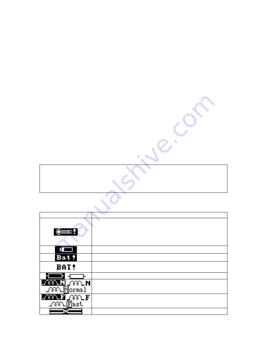
Additional information displayed by the meter
Information
Comment
The maximum acceptable temperature inside the meter has
been exceeded. The thermal protection blocks measurements.
Additionally the following is displayed:
Overheated!
T>T
max
and
there are two long sound signals
after the
START
button is
pushed.
Indication of the charge of accumulators.
Accumulators are low, they must be charged.
Accumulators completely discharged, the measurement is
blocked.
Symbols of a resistance-type object.
Symbols of an inductive object (normal measurement time for
this type).
Symbols of (reduced measurement time).
Swapped measurement leads.
Summary of Contents for MMR-630
Page 1: ......
Page 2: ......
Page 3: ......
Page 12: ...OPERATING MANUAL MMR 630 Revision 1 6 9...
Page 27: ...OPERATING MANUAL MMR 630 Revision 1 6 24 4 3 Memory browsing 4 4 Memory erasing...
Page 28: ...OPERATING MANUAL MMR 630 Revision 1 6 25...
Page 38: ...OPERATING MANUAL MMR 630 Revision 1 6 35...
Page 39: ......
Page 40: ......


