background image

OPERATING MANUAL MMR-630   Revision 1.6 

32 

Attachments 

9.1 

Technical data 

The abbreviati

on „m.v.” in the basic error definition means the measured value 


The errors specified in the table refer to measurements realised by means of bidirectional current 

and they are related to the average value of two measurements, in accordance with the following for-
mula: 

2

R

F

R

R

R

,  where R

F


– resistance at the conventional „forward” current, and R

R


– resistance 

at the conventional „backward” current. In the case of measurements with single-direction current and 

for  measurements  of  inductive  objects  at  a  reduced  measurement  time  (symbol 

F

)  the 

specified precision is not guaranteed.  

 
Measurement of resistance  

Range  

Resolution 

Basic uncertainty   

Current 

0...999,9




0,1




(0,25% m.v. + 2 digits) 

10A 

1,0000...1,9999m


0,0001m


2,000...19,999m


0,001m


20,00...199,99m


0,01m


1A 

200,0...999,9m


0,1m


0,1A 

1,0000...1,9999


0,0001


2,000...19,999


0,001


10mA 

20,00...199,99


0,01


1mA 

200,0...


1999,9


0,1


0,1mA 


Input voltmeter impedance: 

200k


Measurement resistance at a 50Hz noise 

Measured 

resistance 

Noise level 

Additional uncer-

tainty   

Measurement 

blocked 

<0,2m

Ω


15...100mV 

1% 

<0,2m

Ω


>100mV 

YES 

0,2m

Ω


100mV...0,5V 

1% 

0,2m

Ω


>0,5V 

YES 

 
Other technical data

:


a)  Kind of insulation: ...................................................... double, in accordance with EN 61010-1:2004 
b)  Measurement category ....................................................................................................................  

 ..... III 300V (< 2000m above sea level), III 260V (< 3000m above sea level) EN 61010-1 compliant 

c)  Protection grade of the casing in accordance with EN 60529 ................................................... IP54 
d)  Protection from external voltage ......................................................................up to 440Vac for 10s 
e)  Power supply of the meter ......................... package of ACCUMULATORS SONEL/NiMH 4,8V 3Ah 
f)  Power supply of the charger ................................................................ 100..250V/50..60Hz, 200mA 
g)  Charging time .............................................................................................. approximately 2,5hours 
h)  Number of measurements with 10A current ............................................................................... 300 
i) 

Maximum resistance of leads for 10A current .......................................................................... 0,1


j) 

Maximum inductivity of the tested object ................................................................................... 40H 

k)  Exactitude of the measurement current  ................................................................................. 

10% 

l) 

Duration of measurements of resistance: 
in case of resistance-type objects and bidirectional current ........................................................ 3 s 


Summary of Contents for MMR-630

Page 1: ......

Page 2: ......

Page 3: ......

Page 4: ...LOW RESISTANCE METER MMR 630 OPERATING MANUAL SONEL S A ul Wokulskiego 11 58 100 widnica Revision 1 6 February 14 2017...

Page 5: ...hased our low resistance meter The MMR 630 meter is a modern high quality measuring device which is easy and safe to use Please acquaint yourself with the pre sent manual in order to avoid measuring e...

Page 6: ...TURER AND THE PROGRAMME 13 3 MEASUREMENTS 14 3 1 CONFIGURATION OF THE MEASUREMENT OPTIONS 14 3 1 1 Selection of the type of object 14 3 1 2 Flow of current 15 3 1 3 Measurement triggering 15 3 1 4 Sav...

Page 7: ...PERATING MANUAL MMR 630 Revision 1 6 4 7 STORAGE 31 8 DISMANTLING AND UTILIZATION 31 9 ATTACHMENTS 32 9 1 TECHNICAL DATA 32 9 2 STANDARD ACCESSORIES 33 9 3 ADDITIONAL ACCESSORIES 33 9 4 MANUFACTURER 3...

Page 8: ...icular type of work Before starting the work with the device in special environments e g potentially fire risk explosive environment it is necessary to consult it with the person responsible for healt...

Page 9: ...OPERATING MANUAL MMR 630 Revision 1 6 6 2 Menu The menu is available at any position of the knob but MEM...

Page 10: ...an authorised distributor The accessories may be used in case of many devices manufactured by SONEL S A which are equipped with the RS 232 interface Detailed information regarding software is availab...

Page 11: ...gnalled by two long sound sig nals and the symbol R Rmax or R Rmin displayed instead of the result In the mode of manual saving of the result in the memory the limits are displayed in place of the ban...

Page 12: ...OPERATING MANUAL MMR 630 Revision 1 6 9...

Page 13: ...re established 2 6 Default settings The default settings are the following Type of the object resistance object selection of the measurement range automatic flow of current bidirectional trigering mo...

Page 14: ...8 Advanced functions 2 8 1 Manual calibration The user may perform manual calibration of the meter provided they have standard resistors minimum grade 0 05 of the following nominal values 0 2m 2m 20m...

Page 15: ...er to return to the default calibration enter this option in the MENU and select YES and con firm pressing This option erases the results of manual calibration and auto calibration realised by the use...

Page 16: ...harge the accumulators During programming do not turn the meter off or disconnect the transmission cable During programming the only active button is In the case of this function the meter does not tu...

Page 17: ...indispensable to perform correct meas urements of resistance of highly inductive objects In this mode the duration of the measurement de pends upon the inductance of the object since the meter automat...

Page 18: ...urrent is selected the resistance value RR is not displayed 3 1 3 Measurement triggering The MMR 630 meter has three modes of measurement triggering normal automatic and contin uous In the normal mode...

Page 19: ...atic measurement triggering mode is not active 3 1 4 Saving to memory Automatic saving of the measurement results to memory may be particularly useful in the automat ic and continuous measurement trig...

Page 20: ...nts In this mode the setting of the rotary knob determined the selected measurement current Notes If resistance type object is selected solely the automatic range selection is active Manual selection...

Page 21: ...OPERATING MANUAL MMR 630 Revision 1 6 18 The appearance of the screen may differ depending on the configuration of MENU Measure ment mode...

Page 22: ...Revision 1 6 19 During the measurement a moving horizontal line is displayed The measurement may be inter rupted pressing button ESC Depending on the measured object the measurement may last between 3...

Page 23: ...er will display the result with a one grade down resolution If the value of the measured resistance is within the limit of subranges it may happen that the value measured for single direction current...

Page 24: ...measurement regarding a temporary overflow of the measure ment range during charging an inductive object Voltage on the object A message with a long sound signal means the voltage at the terminals U1...

Page 25: ...cretion assign cell numbers to specific measurement points and numbers of the banks to specific objects as well as per form measurements in any order and repeat them not loosing the other data The mem...

Page 26: ...screen and three short sound signals After information is saved in the last cell in the given bank the following message is displayed Last cell in bank 4 2 Automatic saving of measurement results in t...

Page 27: ...OPERATING MANUAL MMR 630 Revision 1 6 24 4 3 Memory browsing 4 4 Memory erasing...

Page 28: ...OPERATING MANUAL MMR 630 Revision 1 6 25...

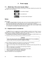
Page 29: ...have a series of advantages such as lack of harmful substances no memory effect higher capacity as compared to NiCd accumulators at the same size The package of accumulators is placed in a compartmen...

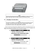
Page 30: ...of accumulators may commence solely when the meter is off When it is turned on using the button the charging function is blocked The AUTO OFF function in the charging mode is deactivated When the char...

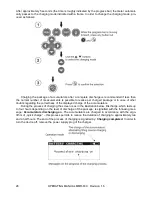
Page 31: ...other doubts regarding the correctness of the displayed charge of the accumulators During the process of charging the screen is as in the illustration below Discharge which lasts up to four hours dep...

Page 32: ...ly in such a temperature Place the meter in a warm place and commence the charging mode anew The present message may be displayed also in the case of deep discharging of the ac cumulators It is then r...

Page 33: ...rt of the process of charging which might damage the accumulator irreparably An increase of the temperature of the accumulator is a signal to stop charging and is a typical phenomenon However charging...

Page 34: ...he case the meter is to be stored for a prolonged period of time the accumulators must be removed from the device The acceptable storage temperatures are those indicated in the technical specification...

Page 35: ...9999 0 0001 2 000 19 999 0 001 10mA 20 00 199 99 0 01 1mA 200 0 1999 9 0 1 0 1mA Input voltmeter impedance 200k Measurement resistance at a 50Hz noise Measured resistance Noise level Additional uncer...

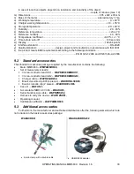
Page 36: ...e following standards EN 61326 1 2006 and EN 61326 2 2 2006 9 2 Standard accessories The standard accessories package supplied by the manufacturer contains the following Meter MMR 630 WMPLMMR630 Set o...

Page 37: ...PE Kalkulacje software to create measurement calculations Note The software is supported by the following systems Windows XP Service Pack 2 Windows Vista Windows 7 9 4 Manufacturer The manufacturer of...

Page 38: ...OPERATING MANUAL MMR 630 Revision 1 6 35...

Page 39: ......

Page 40: ......

Reviews: