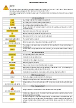
MEASURING MESSAGES
NOTE!
The MPI-535 meter is designed for operation at rated phase voltages of 110 V, 115 V, 127 V, 220 V, 230 V and 240 V
and phase-to-phase voltages of 190 V, 200 V, 220 V, 380 V, 400 V, 415 V.
Connecting voltage higher than allowed between any of the test terminals may damage the meter and cause a hazard
to the user.
Z
S
measurement
U
L-N
voltage is incorrect for making a measurement.
U
L-PE
voltage is incorrect for making a measurement.
U
N-PE
voltage exceeds allowable value of 50 V.
Phase connected to N terminal instead of L terminal (for example, exchange of L and N in
the mains socket).
Maximum temperature of the meter is exceeded.
Network frequency is outside the range of 45...65 Hz.
Measurement error. Correct result cannot be displayed.
Loop circuit malfunction!
The meter should be serviced.
and continuous audio signal
Before measurement, voltage at test terminals exceeds 500 V.
The voltage on the tested object is not within the limits specified for the set rated voltage of
the network U
n
.
Too low value of the prospective short circuit current I
k
for the pre-set fuse and time of its trig-
gering.
R
E
measurement
Too high voltage at the meter terminals.
Interruption in the test probe circuit.
Interruption in the voltage probe circuit.
R
E
>1.99 kΩ
Measuring range is exceeded.
Signal / noise ratio is too low (interfering signal too large).
Measurement uncertainty R
E
due to the resistance of electrodes >30 %. (For calculating un-
certainty, measured values are taken into account).
Interruption in measuring circuit or resistance of test probes is higher than 60 kΩ.
RCD measurement
U
B
>U
L
!
The touch voltage exceeds a preset U
L
threshold value.
!
displayed on the right side of the result indicates a fault of RCD.
and continuous audio signal
Voltages between the contact electrode and PE conductor exceeds the allowable limit value
of U
L
.
R
ISO
measurement
and continuous audio signal
Voltage detected on terminals of the meter. Measurement is not possible.
Interference voltage occurs on the tested object. Measurement is possible but may be bur-
dened with additional uncertainty.
Current limit tripped. The symbol displayed during the measurement is accompanied by a
continuous beep. If it is displayed after the measurement, it means that the measurement re-
sult was obtained during operation with a current limiting device (e.g. short circuit of the test
object).


