background image


MPI-535 

– BRIEF USER MANUAL 

Security 


MPI-535 meter is designed for performing check tests of protection against electric shock in 

AC  mains  systems  and  recording  mains  systems  parameters.  The  meter  is used for performing 
measurements  and  providing  results  to  determine  the  level  safety  of  electrical  installations. 
Therefore,  in  order  to  provide  conditions  for  correct  operation  and  accuracy  of  obtained  results, 
the following recommendations must be observed: 


Before  you  proceed  to  operate  the  meter,  familiarise  yourself  thoroughly  with  this   manual  
and observe the safety regulations and specifications provided by the manufacturer.  


Any application that differs from those specified in this manual may result in a damage to the 
device and constitute a source of danger for the user. 


MPI-535 meters must be operated only by appropriately qualified personnel with relevant cer-
tificates authorising the personnel to perform works on electric systems. Unauthorized use of 
the meter may result in its damage and may be a source of serious hazard to the user. 


Using  this  manual  does  not exclude the need to comply with occupational health and safety 
regulations and with other relevant fire regulations required during the performance of a par-
ticular type of work. Before starting the work with the device in special environments, e.g. po-
tentially fire-risk/explosive environment, it is necessary to consult it with the person responsi-
ble for health and safety. 


It is unacceptable to operate: 

  a damaged meter which is completely or partially out of order, 

  a meter with damaged insulation,


  a meter stored for an excessive period of time in disadvantageous conditions (e.g. excessive 

humidity). If the meter has been transferred from a cool to a warm environment with a high 
level of relative humidity, do not start measurements until the meter is warmed up to the am-
bient temperature (approximately 30 minutes).


If the battery is discharged to a level preventing further measurements, the meter displays an 
appropriate message and then turns off. 


Battery spill and damage to the meter may occur if discharged batteries are left in the meter. 


Before measurement, make sure that test leads are connected to appropriate measuring ter-
minals. 


Do not operate a meter with an open or incorrectly closed battery (accumulator) compartment 
or power it from other sources than those specified in the present manual. 


R

ISO

  meter  inputs  are  electronically  protected  against  overloads  (caused  by  e.g.  connecting 

the meter to a live circuit) up to 463 V RMS for 60 seconds.  


Repairs may be performed only by an authorised service point. 


NOTE! 
 

Only standard and additional accessories for a given device should be used, as listed 
in 

section 8

Using other accessories may cause damage to measuring terminals, in-

troduce additional measurement errors and create a risk for the user. 


Due to continuous development of the meter’s software, the actual appearance of the 
display, in case of some of the functions, may differ from the display presented in this 
operating manual. 


Summary of Contents for MPI-535

Page 1: ......

Page 2: ...4...

Page 3: ...EF USER MANUAL METER FOR ELECTRICAL INSTALLATION PARAMETERS MPI 535 SONEL S A Wokulskiego 11 58 100 widnica Full version of the manual is provided on the website www sonel pl en Version 1 01 1 11 03 2...

Page 4: ...15 3 3 4 Measurement of resistance to earth using double clamp method 16 3 4 Measuring soil resistivity 17 3 4 1 Settings of measurements 17 3 4 2 Soil resistivity measurements 18 3 5 Measurement of...

Page 5: ...E ZL N ZL L 34 7 1 4 Measurement of fault loop impedance ZL PE RCD without triggering of RCD 35 7 1 5 Measurement of parameters of RCD 35 7 1 6 Measurement of resistance to earth RE 36 7 1 7 Low volta...

Page 6: ...e person responsi ble for health and safety It is unacceptable to operate a damaged meter which is completely or partially out of order a meter with damaged insulation a meter stored for an excessive...

Page 7: ...ot in the slot the icon on the screen is crossed out Wireless network signal strength Battery discharge indicator Active menu help Tapping a selected main menu item redirects to the sub menu Available...

Page 8: ...me and display brightness can be set from the Meter settings screen In the main menu select Settings Select Meter settings 2 2 Measurement settings From the Measurement settings menu it is possible to...

Page 9: ...arth measurements This selection ensures optimum interference filtering The meter is designed for filtration of inter ferences generated by 50 Hz and 60 Hz networks Setting Auto increment as active pl...

Page 10: ...ents WARNING During measurements fault loop RCD do not touch conductive accessible or foreign parts of the tested electrical installation The following tests are available from the Measurements menu f...

Page 11: ...will generate a continuous audio signal This option is available for all measuring functions that apply to residual current devices RCD and fault loop except ZL N measurement WARNING When phase volta...

Page 12: ...PE RCD 3 2 1 Measurement of fault loop parameters in the L N and L L circuits Connect test leads according to the drawing or for measurement in the L N circuit for measurement in the L L circuit Selec...

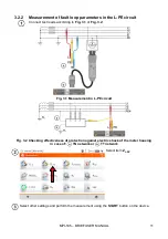
Page 13: ...leads according to Fig 3 1 or Fig 3 2 Fig 3 1 Measurement in L PE circuit Fig 3 2 Checking effectiveness of protection against electric shock of the meter housing in case of TN network or TT network...

Page 14: ...t loop impedance in L PE circuit protected with a residual current device RCD Connect test leads according to Fig 3 3 Fig 3 4 or Fig 3 5 Fig 3 3 Measurement in the TN S system Fig 3 4 Measurement in t...

Page 15: ...asurement settings menu NOTE After selecting an IT type network the function of the contact electrode is inactive When attempting to perform the ZL PE and ZL PE RCD measurement a message will appear i...

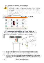
Page 16: ...arth using 3P method The three pole measuring method is the basic type of resistance to earth measurement Disconnect earth electrode being tested from the installation of the building Drive the curren...

Page 17: ...ctrode into the ground and connect to the H socket of the meter Drive the voltage electrode into the ground and connect to the S socket of the meter The earth electrode being tested should be connecte...

Page 18: ...35 BRIEF USER MANUAL 16 Select the 4P option in the measurement menu Select other ones and perform the measurement using the START button 3 3 4 Measurement of resistance to earth using double clamp me...

Page 19: ...RT button 3 4 Measuring soil resistivity For soil resistivity measurements used as preparation for the designing the earthing system or in geology measurements a separate function is provided measurem...

Page 20: ...ity measurements Drive 4 probes into the ground in one line and at equal distances Connect the probes to the meter according to the drawing above Call up the measurement menu Select other settings and...

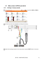
Page 21: ...surement of RCD parameters 3 5 1 Settings of measurements Select item RCD IA or RCD tA Connect the meter to the installation according to the drawing Select other settings and perform the measurement...

Page 22: ...s section 2 2 1 NOTE After selecting an IT type network the function of the contact electrode is inactive The manner of connecting the device to the installation is shown in Fig 3 7 and Fig 3 8 Fig 3...

Page 23: ...obey the above instruction will lead to high voltage elec tric shock and make it impossible to discharge the tested object 3 6 1 Settings of measurements Select item RISO Connect the meter probe or th...

Page 24: ...MPI 535 BRIEF USER MANUAL 22 Measurement using probes Measurements using UNI Schuko adapter WS 03 and WS 04 Measurements using AutoISO 1000c adapter...

Page 25: ...measurement screen Connect the meter to the tested object Measurement starts automati cally During the measurement the H V REC CONT diode is lit green and a sound signal is emitted NOTE Display of sy...

Page 26: ...bonding with 200 mA current Select item RCONT to call up the measurement screen Connect the meter to the tested object Measurement starts automati cally NOTE Display of symbols indicates that the test...

Page 27: ...em 1 2 3 to call up the measurement screen Connect the meter to the installation according to the drawing The phase sequence is correct i e the phase sequence is in clockwise direction The phase seque...

Page 28: ...35 BRIEF USER MANUAL 26 3 9 Illuminance measurements Select item Lux meter to call up the measurement screen Connect the optical probe and place it in the tested plane The meter will show the measure...

Page 29: ...no need to trig ger each measurement by pressing START button The role of the user is reduced to initiating the measurement by single pressing START and switching RCD on after each tripping 4 1 Settin...

Page 30: ...with increasing head is forced current with decreasing head is forced x0 5 1 2 5 a multiplicity of RCD rated current accord ing to IEC 61557 6 Select the metering mode full standard If full mode has b...

Page 31: ...MANUAL 29 4 2 Automatic measurement of RCD Connect the meter to the installation according to the drawing Select RCDAUTO Enter the measurement settings in accordance with section 4 1 Press START to st...

Page 32: ...for all types of RCD tA at 1 I n tA 300 ms for general purpose RCDs tA at 2 I n tA 150 ms for general purpose RCDs tA at 5 I n tA 40 ms for general purpose RCDs tA at 1 I n 130 ms tA 500 ms for selec...

Page 33: ...settings restores the meter memory to default memory settings When this op tion has been selected a prompt will appear asking the user to confirm the selection SD card format When this op tion has bee...

Page 34: ...tored in one cell of the Measurement points column Only the results of measurements activated by pressing the START button can be stored in the memory except autozeroing in low voltage measurement of...

Page 35: ...er supply adapter charging cable for the car cigarette lighter Charging is indicated by the icon next to the battery symbol on the top bar and by the H V REC CONT diode The temperature of the battery...

Page 36: ...t In a domestic environment this product may cause ra dio interference in which case the user may be required to take adequate measures e g increasing the distance between affected products 7 1 Basic...

Page 37: ...ing of RCD Measurement of fault loop impedance ZS Test range according to IEC 61557 3 0 50 1999 for 1 2 m leads WS 03 and WS 04 0 51 1999 for 5 m 10 m and 20 m leads Display range Resolution Basic unc...

Page 38: ...61557 5 0 50 1 99 k for test voltage of 50 V oraz 0 56 1 99 k for test voltage of 25 V Range Resolution Basic uncertainty 0 00 0 35 0 01 2 m v 10 digits 0 35 9 99 0 01 2 m v 4 digits 10 0 99 9 0 1 2 m...

Page 39: ...ity of protective conductors and equipotential bonding with 200 mA current Measurement range according to IEC 61557 4 0 12 400 Range Resolution Basic uncertainty 0 00 19 99 0 01 2 m v 3 digits 20 0 19...

Page 40: ...ncertainty 0 k 1999 k 1 k 3 m v 8 digits 5 m v 8 digits 2 00 M 19 99 M 0 01 M 20 0 M 199 9 M 0 1 M 200 M 999 M 1 M for WS 03 and WS 04 leads Test range according to IEC 61557 2 for UN 500 V 500 k 2 00...

Page 41: ...inty 0 399 9 0 1 f1 6 5 m v 5 digits 400 3999 1 4 00 k 19 99 k 0 01 k Probe class B Measuring ranges of LP 10B probe Range lx Resolution lx Spectral uncertainty Basic uncertainty 0 39 99 0 01 f1 6 5 m...

Page 42: ...WAPRZ030REBBSZ transmission lead with USB plugs WAPRZUSB crocodile clip 1 kV 20 A cat III 1000 V 3 pcs yellow K02 WAKROYE20K02 red K02 WAKRORE20K02 blue K02 WAKROBU20K02 test prod with banana socket c...

Page 43: ...t fuse and time of its trig gering RE measurement Too high voltage at the meter terminals Interruption in the test probe circuit Interruption in the voltage probe circuit RE 1 99 k Measuring range is...

Page 44: ......

Reviews: