MRU-120
– USER MANUAL
40
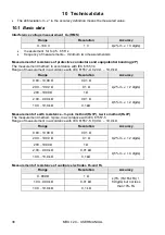
v) temperature range suitable for initiating battery charging ....................................... +10
C to +40
C
w) temperatures at which loading is interrupted ............... below +5
C and above (or equal to) +50
C
x) reference temperature .......................................................................................................
23 ±2
C
y) storage temperature.......................................................................................................-20..+80
C
z) relative humidity .................................................................................................................20..85%
aa) relative humidity nominal ...................................................................................................40..60%
bb) altitude (above sea level) ................................................................................................
≤2000 m*
cc) quality standard ............................................. design and production in accordance with ISO 9001
dd) the product meets EMC requirements according to the following standards ..................................
...................................................................................................... EN 61326-1 and EN 61326-2-2
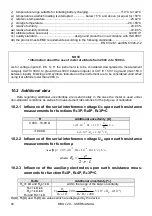
NOTE
* Information about the use of meter at altitude from 2000 m to 5000 m
As for voltage inputs E, ES, S, H the instrument is to be considered downgraded to measurement
category CAT III 300 V to ground (max 300 V between inputs) or CAT IV 150 V to ground (max 150 V
between inputs). Markings and symbols indicated on the instrument are to be considered valid when
using it at altitude lower than 2000 m.
10.2 Additional data
Data regarding additional uncertainties are useful mainly in the case the meter is used under
non-standard conditions as well as for measurement laboratories for the purpose of calibration.
10.2.1 Influence of the serial interference voltage U
N
upon earth resistance
measurements for functions R
E
3P, R
E
4P, R
E
3P+C
R
Additional uncertainty [
Ω]
0,000…19,99 Ω
N
E
N
E
U
R
U
R
)
10
2
10
25
(
4
4
>19,99
Ω
N
E
U
R
)
10
2
10
5
(
2
4
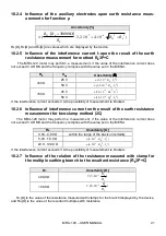
10.2.2 Influence of the serial interference voltage U
N
upon earth resistance
measurements for function
ρ
add
[
Ω] =
N
N
H
E
U
U
R
R
)
10
10
(
5
,
2
6
3
,
where
L
R
E
2
10.2.3 Influence of the auxiliary electrodes upon earth resistance meas-
urements for function R
E
3P, R
E
4P, R
E
3P+C
R
H
,R
S
Additional uncertainty [%]
R
H
≤1 kΩ and R
S
≤1 kΩ
within the range of the basic uncertainty
R
H
>1
kΩ lub
R
S
>1
kΩ lub
R
H
and R
S
>1
kΩ
)
10
4
10
5
200
200
10
(
4
3
2
6
H
H
E
H
S
S
R
R
R
R
R
R
R
E
[Ω], R
S
[Ω] and R
H
[Ω] are values which are displayed by the device.
Summary of Contents for MRU-120
Page 1: ......
Page 2: ...MRU 120 USER MANUAL 2 ...
Page 48: ...MRU 120 USER MANUAL 46 NOTES ...
Page 49: ...MRU 120 USER MANUAL 47 NOTES ...
Page 50: ...MRU 120 USER MANUAL 48 NOTES ...
Page 51: ......
Page 52: ...MRU 120 USER MANUAL 2 ...

