background image

MRU-200-GPS OPERATING MANUAL  Version 1.06 

11 

Note: 

 
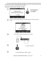
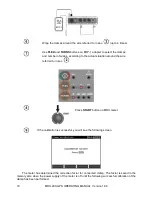
- Make sure the test lead E 

– H passes through the center of the clamp or probe. 


Additional information displayed by the meter 


Message 

Cause 

Procedure 

ERROR: CLAMP NOT CONNECTED 
OR NOT PUT ON WIRE 
CONNECTED TO H AND E SOCKET! 

The clamp is not 
connected 

Check whether the 
clamp is connected 
to the device or 
whether it is placed 
upon the test lead 
used by the meter 
to force the pas-
sage of current. 

ERROR: WIRE NOT CONNECTED 
TO H AND E TERMINAL! 
CALIBRATION ABORTED. PRESS 
ENTER 

No wire 

Revise the connec-
tions 

ERROR: CALIBRATION 
COEFFICIENT OUT OF RANGE. 
CALIBRATION ABORTED. PRESS 
ENTER 

Incorrect calibra-
tion factor 

Check the quality of 
the connections 
and/or replace the 
clamp. 


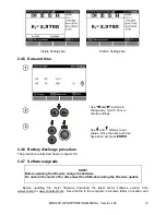
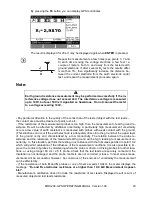
2.3.3  Ground resistivity settings 


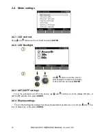
Using  ,  , 

 and 


buttons select the desired op-
tions for distance units and 
press  

ENTER

.


Summary of Contents for MRU-200-GPS

Page 1: ......

Page 2: ......

Page 3: ...OPERATING MANUAL EARTH GROUND RESISTANCE METER MRU 200 GPS SONEL TEST MEASUREMENT Inc Santa Clara Ca USA SONEL S A widnica Poland Version 1 06 Apr 12 2017...

Page 4: ...ipment is operated in a commercial envi ronment This equipment generates uses and can radiate radio frequency energy and if not installed and used in accordance with the instruction manual may cause h...

Page 5: ...ION ON THE MANUFACTURER 14 3 MEASUREMENTS 14 3 1 MEASUREMENT OF EARTH CONNECTION AND EQUIPOTENTIAL BONDING 2P 14 3 2 CALIBRATION OF THE TEST LEADS 16 3 2 1 Auto zeroing on 16 3 2 2 Auto zeroing off 17...

Page 6: ...e measurements for function 3P 4P 3P clamp 55 10 2 4 Influence of the auxiliary electrodes upon earth resistance measurements for function 56 10 2 5 Influence of the auxiliary electrodes upon earth re...

Page 7: ...nments etc always consult first with the person responsible for health and safety Do not operate the meter If the meter is completely or partially malfunctioning If the meter has damaged test leads or...

Page 8: ...s available at any position of the knob Press MENU Using and buttons highlight the required position Press ENTER to select the option 2 1 Wireless transmission See chapter 5 3 2 2 GPS settings Using b...

Page 9: ...equency must be set in the meter since it is the source of potential interference with resistance measurements due to stray electrical fields The meter will pick the appropriate frequency of its measu...

Page 10: ...i current probe The clamp or probe must be calibrated before using for the first time It is advisable to periodically calibrate the clamp or probe so age effects will not influence the resolution of m...

Page 11: ...hed off In any subsequent calibra tion of a clamp or probe the calibration data will be updated Calibration of flexible clamps using ERP 1 adapter After reading the intro ductory information press ENT...

Page 12: ...s according to the actual situation around the wire referred to in sec Press START button on MRU meter If the calibration is successful you will see the following screen The meter has determined the c...

Page 13: ...amp is connected to the device or whether it is placed upon the test lead used by the meter to force the pas sage of current ERROR WIRE NOT CONNECTED TO H AND E TERMINAL CALIBRATION ABORTED PRESS ENTE...

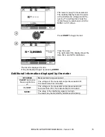
Page 14: ...e time for LCD backlight to remain on Always or shut off time and press ENTER 2 4 3 AUTO OFF settings To set the automatic turn off of the device use and buttons to set the display ON time or AUTO OFF...

Page 15: ...press ENTER 2 4 6 Battery discharge procedure The procedure is fully described in chapter 6 5 2 4 7 Software upgrade NOTE Before updating the firmware charge the batteries Do not turn the meter off or...

Page 16: ...ess ENTER 2 6 Information on the manufacturer Use and buttons in order to select Product info and press ENTER 3 Measurements Note During measurements the status bar is displayed 3 1 Measurement of ear...

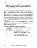
Page 17: ...shows the date time and GPS coordinates The result is displayed for 20s It may be displayed again by pressing ENTER Additional information displayed by the meter R 19 99k Measurement range exceeded VN...

Page 18: ...ad resistance The measurement function 2P includes the AUTOZERO sub function 3 2 1 Auto zeroing on Turn the meter on Set the rotary function selector switch at 2P Press F1 Follow the displayed instruc...

Page 19: ...ll be not be displayed on the right hand side of the display Note Auto zero compensation needs only be enabled once for a given set of test leads The last compen sation values are remembered when the...

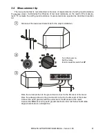
Page 20: ...e the voltage probe into the ground and connect to the S socket of the meter Connect the earth ground electrode under test to the E socket of the meter Align all electrodes in a straight line The mete...

Page 21: ...n you can display GPS coordinates The result is displayed for 20s It may be displayed again by pressing ENTER S Repeat the measurements a few times see points 3 7 and 8 each time moving the voltage pr...

Page 22: ...ch will permit evaluation of the influence of the measurement conditions It is also possible to im prove the contact of probes by moistening where the probe is driven or driving probes into other loca...

Page 23: ...ed in section 3 9 Disconnect the tested earth electrode for the object installation Turn the meter on Set the rotary function selector switch at 4P E S H E ES S H CAT IV 300V ES Drive the current prob...

Page 24: ...e and its fre quency The settings bar shows the mains frequency set in the MENU Press F1 to select the measuring voltage Use and buttons to set the measuring voltage and press ENTER Press START to beg...

Page 25: ...high measurement uncertainty occurs a low value of earth resistance is measured with probes with weak contact with the ground This situation can occur if the earth electrode is adequately driven into...

Page 26: ...h the result may be distorted by additional uncertainty 3 5 Measurement 3p clamp Turn the meter on Set the rotary function selector switch at 3P E S H CAT IV 300V Drive the current probe into the grou...

Page 27: ...sion 1 06 25 Press button F2 to select measurement with a C 3 current clamp Use and buttons to select C 3 clamp and press ENTER Press F1 to select the measuring volt age Use and buttons to set the mea...

Page 28: ...played again when ENTER is pressed S Repeat the measurements a few times see points 2 and 5 each time moving the voltage probe a few feet a couple of meters both to and away from the tested earth grou...

Page 29: ...ment un certainty In this situation perform the testing in accordance with the formulae specified in point 10 2 which will permit evaluation of the influence of the measurement conditions It is also p...

Page 30: ...obe into the ground and connect to the S socket of the meter Connect the first leg of the pylon to be tested to the E socket of the meter Align the leg of the pylon under test the current electrode an...

Page 31: ...MRU 200 GPS OPERATING MANUAL Version 1 06 29 Use buttons to select the meas urement with ERP 1 press ENTER Press F3 button to select the number of pylon legs...

Page 32: ...leg of the pylon if not al ready done To start the measurement press START again After the measurement of the first leg of the pylon the measured re sistance value of the tested leg is shown on the ma...

Page 33: ...seconds the meter will then display the resultant earth resistance RE Use buttons and to change results displayed in the window on the right side of the screen 3 7 Two clamp measurement Two clamp meas...

Page 34: ...1 ft 30cm from each other as shown The meter is ready for measurement The auxiliary display shows the value of the leakage current passing through the measurement clamp with split core C 3 and its fre...

Page 35: ...t of the dynamic impedance of light ning arrester earthing systems It must not be used for the purpose of measurements of protective and working earthing systems Due to the high steepness of the test...

Page 36: ...H E Drive the current probe into the ground and connect to the H socket of the meter Drive the voltage probe into the ground and connect to the S socket of the meter Connect the earth ground electrode...

Page 37: ...y for measurement The auxiliary display shows the value of the interference voltage and its frequen cy The settings bar shows the pulse shape i e rise time and duration Press F1 to modify the pulse sh...

Page 38: ...the tested object with the test leads the contact area must be cleaned of paint rust etc If the resistance of the measurement probes is too high then the measurement of earth ground re sistance RE wi...

Page 39: ...nuous audio tone The voltage on the measurement points exceeds 40V the measurement is cancelled VN 24V The voltage on the measurement points exceeds 24V but lower than 40V the measurement is cancelled...

Page 40: ...iminary measurements for the design of earth ground system installations or for geological studies The function is metrologically identical to the four pole earth ground resistance measurement but inc...

Page 41: ...ry display shows the value of the interference voltage and its fre quency The settings bar shows the measurement voltage mains frequency set in the MENU and the distance be tween the electrodes Press...

Page 42: ...the resistance of the probes By pressing the F4 button you can display GPS coordinates The result is displayed for 20s It may be displayed again when ENTER is pressed Notes Earth ground resistance me...

Page 43: ...are not corroded or loose In most cases meas urements will be successful however be conscious of the sources of uncertainty the measurement can be affected by If the resistance of H and S probes or on...

Page 44: ...measurement has finished press ENTER Empty cell Occupied cell Cells are selected via the and buttons Banks are selected is via the and buttons To save press ENTER If the cell is occupied the followin...

Page 45: ...ersion 1 06 43 4 2 Erasing Memory Note During the process of erasing memory the progress bar is displayed Turn the meter on Set the rotary function selector switch at MEM Using the and buttons highlig...

Page 46: ...ess ENTER Use the and buttons to select a bank and the and buttons to select a cell Note During a memory search only those cells that contain data are listed empty cells and banks are skipped and are...

Page 47: ...Reader software The software can also be downloaded from www soneltest com or www sone pl 5 2 Connection of the meter to a computer 1 Set the rotary function selector switch at MEM 2 Connect the cable...

Page 48: ...er PIN code compatible with the PIN code of the meter defined in main settings 4 On the computer start data storing programme If a PIN code change is necessary select Modify PIN code Set the required...

Page 49: ...tery charged Battery low Battery fully discharged Battery fully discharged Measurements cannot proceed Note The displayed BAT symbol means insufficient power supply voltage and the batteries need to b...

Page 50: ...acement Remove the battery compartment to get access to two replaceable fuses FST 250Vac 1A 5x20mm and 2A 250Vac time delay fuse 5x20mm If the instrument or battery charger does not work before sendin...

Page 51: ...e contacts of the battery package Should the problem persist replace the battery Battery temperature too low The ambient tem perature is lower than 10 C It is not possible to charge the batteries at l...

Page 52: ...ces However it is recommended to discharge them completely periodically During storage Ni MH batteries discharge at a rate of approximately 30 per month High tempera tures accelerates discharge To pre...

Page 53: ...emove the batteries if the meter is stored for long periods To prevent total discharge of the batteries in prolonged periods of storage re charge them peri odically 9 Dismantling and disposal Disused...

Page 54: ...0 to 39 99 0 01 2 m v 2 digits 40 to 399 9 0 1 400 to 3999 1 4 000 to 19 99k 0 01k 5 m v 2 digits In 0 000 to 0 045 range uncertainty is unspecified Measurement of earth resistance 3 4 cable method Th...

Page 55: ...Wenner s 2 LRE Range Resolution Basic uncertainty 0 0 to 199 9 m 0 1 m Depends on the basic un certainty of the RE 4P measurement but not less than 1 digit 200 to 1 999 m 1 m 2 00 to 19 99k m 0 01k m...

Page 56: ...for 3P 4P 25 or 50 V j Measurement current short circuit current for 3P 4P 200 mA k Maximum resistance of measurement electrodes 20 k l Insufficient clamp current level 0 5 mA m Power supply of the me...

Page 57: ...earth resistance meas urements for function 3P 4P 3P clamp RE RH RS Additional uncertainty 0 000 to 3 999 RH 500 and RS 500 within the range of the basic uncertainty RH 500 or RS 500 or RH and RS 500...

Page 58: ...RE RS and RH are values which are displayed by the device 10 2 5 Influence of the auxiliary electrodes upon earth resistance meas urements by means of the percussive method RH ZE Uncertainty RH 150 0...

Page 59: ...3 2 3 w C R R 99 9 10 6 2 2 w C R R RC is the value of the resistance measured with clamps for the branch displayed by the device and RW is the value of the resultant multiple earth resistance 10 2 9...

Page 60: ...reel with banana plugs at both ends WAPRZ050YEBBSZE Black crocodile clip WAKROBL20K01 Red crocodile clip WAKRORE20K02 Vice WAZACIMA1 Rechargeable batteries WAAKU07 Meter protective cover WAFUTL2 Neck...

Page 61: ...rsion 1 06 59 WACEGFS2OKR Flexible clamp FS 2 WAFUTL3 80cm probe protective cover WAPOJ1 Batteries compartment WACEGFSX3OKR Flexible clamp FSX 3 WAWALXL3 Case XL3 for the meter and accessories LSWGBMR...

Page 62: ...3 Manufacturer The manufacturer of the device which also provides guarantee and post guarantee service is the following company SONEL TEST MEASUREMENT Inc Santa Clara Ca 95054 Tel 408 74 988 1346 Fax...

Page 63: ......

Page 64: ......

Reviews: