MRU-200-GPS OPERATING MANUAL Version 1.06
24
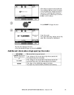
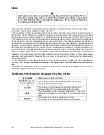
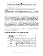
Additional information displayed by the meter
R
E
>19,99k
Ω
Measurement range exceeded.
V
N
>40V!
and a con-
tinuous audio tone
The voltage on the measurement points exceeds 40V,
the measurement is cancelled.
V
N
>24V!
The voltage on the measurement points exceeds 24V
but lower than 40V, the measurement is cancelled.
LIMIT!
The uncertainty of the electrode resistance > 30%. (Un-
certainties calculated on the basis of the measured val-
ues)
NOISE
!
The value of the interfering signal is too high,
the result may be distorted by additional uncertainty.
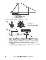
3.5 Measurement 3p + clamp
Turn the meter on.
Set the rotary function selector
switch at
3P
.
E
S H
CA
T
IV
3
00
V
Drive the current probe into the ground and connect to the
H
socket of the meter.
Drive the voltage probe into the ground and connect to the
S
socket of the meter.
Connect the earth ground electrode under test to the
E
socket of the meter.
Align all electrodes in a straight line.
Position the current clamp on the earth ground electrode under test below the
E
cable
connection.
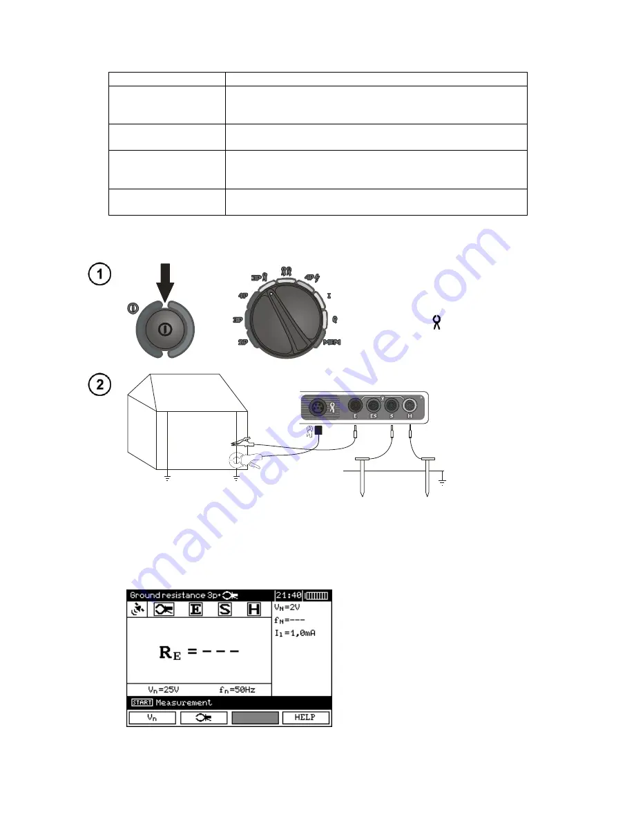
The meter is ready for measurement.
The auxiliary display shows the value of
the interference voltage and its frequen-
cy. The settings bar shows the mains
frequency set in the MENU.

