MRU-200-GPS OPERATING MANUAL Version 1.06
33
Flexible Rogowski current probe must not be used for this measurement.
- Current clamps and probes are not provided as standard accessories and must be purchased
separately.
- Current clamps and probes must be calibrated before use. Calibrate each clamp or probe periodi-
cally to avoid the influence of component ageing upon the resolution of measurements. The calibra-
tion option is in the
MENU
.
- If the clamp current is insufficient, an appropriate message is displayed: "
Measured current is too
low. Measurement impossible!
".
Additional information displayed by the meter
R
E
>149,9
Ω
Measurement range exceeded.
V
N
>40V!
and a con-
tinuous audio tone.
The voltage on the measurement points exceeds 40V,
the measurement is cancelled.
V
N
>24V!
The voltage on the measurement points exceeds 24V
but lower than 40V, the measurement is cancelled.
NOISE
!
The value of the interfering signal is too high,
the result may be distorted by additional uncertainty.
3.8 Measurement 4P (Impulse method)
The impulse method is applied in the case of measurement of the dynamic impedance of light-
ning arrester earthing systems. It must not be used for the purpose of measurements of protective
and working earthing systems.
Due to the high steepness of the test pulse leading edge the inductivity of the earth electrode
highly influences its impedance. Therefore the impedance of the earth electrode measured by means
of the impulse method depends upon its length and the steepness of the test pulse leading edge.
The inductivity of the earth electrode causes a shift between the current spikes and the resultant
voltage drop. Hence extensive earth electrodes of a low resistance measured by means of the low-
frequency method may have a much higher value of the dynamic impedance.
The impulse impedance is calculated on the basis of the following formula:
S
S
E
I
V
Z
Where V
S
, I
S
– peak value of the current and voltage.
The impulse method is used to determine the resultant earth impedance. Therefore the control
measurement points must not be undone.
Note:
Measuring leads must be completely unwound. Otherwise the result of the
measurement may be incorrect.
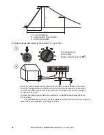
The following illustration explains the numbers which determine the shape of the pulse (in ac-
cordance with EN 62305-1 Lightning protection
– Section 1. General Requirements).


