MRU-200-GPS OPERATING MANUAL Version 1.06
34
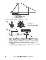
10%
90%
50%
T
1
T
2
t
t = current amplitude
T
1
= pulse leading edge duration
T
2
= time to semi-spike
The pulse shape is determined by the relation T
1
/T
2
eg: 4/10
μs.
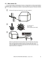
Turn the meter on.
Set the rotary
function selector switch at
4P
.
ES
S
C
AT
IV
3
00
V
H
E
Drive the current probe into the ground and connect to the
H
socket of the meter.
Drive the voltage probe into the ground and connect to the
S
socket of the meter.
Connect the earth ground electrode under test to the
E
socket and the shield of
the
H
cable as shown.
Connect the earth ground electrode under test to the
ES
socket below the
E
ca-
ble as shown.
It is recommended to place the test leads in such a manner that the angle be-
tween them is at least
60°
- see diagram below.

