MRU-200-GPS OPERATING MANUAL Version 1.06
36
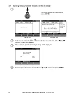
Press
START
to begin measurement.
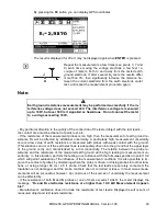
View the result.
Current probe resistance
Voltage probe resistance
Additional uncertainty caused by
the resistance of the probes.
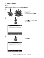
By pressing the
F4
button you can display GPS coordinates.
The result is displayed for 20s. It may be displayed again when
ENTER
is pressed.
Notes:
Earth ground resistance measurement may be performed successfully if the in-
terference voltage does not exceed 24V. The interference voltage is measured
up to 100V, but over 50V is it signalled as hazardous. Do not connect the meter
to a voltage exceeding 100V.
- Pulse shape 8/20
μs is available from firmware version 2.04.
- R
H
i R
S
are measured by means of the low-frequency method.
Pay particular attention to the quality of the connection of the tested object with the test leads
–
the contact area must be cleaned of paint, rust, etc.
- If the resistance of the measurement probes is too high, then the measurement of earth ground re-
sistance R
E
will be affected by additional uncertainty. A particularly high measurement uncertainty
occurs a low value of earth resistance is measured with probes with weak contact with the ground.
(This situation can occur if the earth electrode is adequately driven into the ground but the upper layer
of the ground is dry and characterized by a low conductivity. The relation between the probe re-
sistance and the resistance of the measured earth ground will be high, leading to measurement un-
certainty. In this situation, perform the testing in accordance with the formulae specified in point 10.2
which will permit evaluation of the influence of the measurement conditions. It is also possible to im-
prove the contact of probes by moistening where the probe is driven, or driving probes into other loca-


