background image

MRU-200 

● MRU-200-GPS – USER MANUAL 

19 


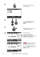
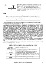
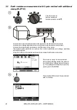
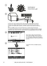
Press 

F1

 to order to modify the 

measuring voltage. 


Use buttons 

 and 

 to set the 

measuring voltage and press 

ENTER


Press 

START

 In order for the test to 

commence measurement. 


Read out the result. 


Current electrode resistance 
Voltage electrode resistance 
Additional  uncertainty  caused  by  the 
resistance of the electrodes 
 
Displayed, when 

δ>30% 


 By pressing the 

F4

 button you can display GPS coordinates. 


The result is displayed for 20 s. It 
may be displayed again when 

ENTER

 is pressed. 

Summary of Contents for MRU-200

Page 1: ......

Page 2: ......

Page 3: ...USER MANUAL EARTH RESISTANCE METER MRU 200 MRU 200 GPS SONEL S A Wokulskiego 11 58 100 widnica Version 2 02 28 07 2021...

Page 4: ...NUAL 2 The MRU 200 MRU 200 GPS meter is a modern easy and safe measuring device Please acquaint yourself with the present manual in order to avoid measuring errors and prevent possible problems relate...

Page 5: ...tance measurement with 3 pole method RE3P 18 3 4 Earth resistance measurement with 4 wire method RE4P 21 3 5 Earth resistance measurement with 3 pole method with additional clamp RE3P C 24 3 6 Earth r...

Page 6: ...measurements for earth resistivity function 55 10 2 5 Influence of the auxiliary electrodes upon earth resistance measurements by means of the impulse method RE4P 55 10 2 6 Influence of the interfere...

Page 7: ...the need to comply with occupational health and safety regu lations and with other relevant fire regulations required during the performance of a particular type of work Before starting the work with...

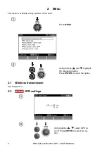
Page 8: ...ilable at any position of the knob Press MENU Using buttons and highlight the required position Press ENTER to select the option 2 1 Wireless transmission See chapter 5 3 2 2 GPS settings Using button...

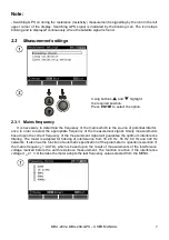
Page 9: ...e source of potential interfer ence in order to select the appropriate frequency of the measurement signal Solely measurements based upon the correct frequency of the measurement signal will guarantee...

Page 10: ...geing elements upon the resolution of measurements The procedure of calibration must be realized also after clamp has been replaced Calibration of hard clamps Having read the preliminary infor mation...

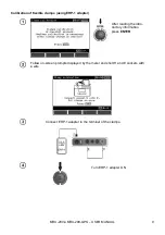
Page 11: ...lexible clamps using ERP 1 adapter After reading the intro ductory information press ENTER Follow on screen prompts displayed by the meter and short H and E sockets with a wire Connect ERP 1 adapter t...

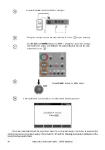
Page 12: ...d number of wraps according to the actual situation around the wire referred to in sec Press START button on MRU meter If the calibration is successful you will see the following screen The meter has...

Page 13: ...d to the device or whether it is placed upon the test lead used by the meter to force the pas sage of current ERROR WIRE NOT CONNECTED TO H AND E TERMINAL CALIBRATION ABORTED PRESS ENTER No wire Revis...

Page 14: ...ttons and set the contrast value and press ENTER 2 4 2 LCD Backlight Use to set the time for LCD backlight shut off and press ENTER to confirm 2 4 3 AUTO OFF settings The setting determines the time b...

Page 15: ...the dis play of the setting bar measurement parameters press ENTER Visible bar Hidden bar 2 4 5 Date and time Use buttons and to select the value to be modified Day month hour minute Use buttons and...

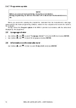
Page 16: ...eb page www sonel pl the meter programming software install it in the computer and connect the meter to the computer Having chosen the Program update in the MENU proceed in accordance with the instruc...

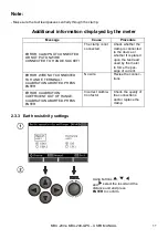
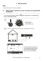
Page 17: ...t complies with the requirements specified in the norm EN 61557 4 U 24 V I 200 mA for R 10 Turn the meter on Set the rotational function selector at 2P Connect the object being measured to the termina...

Page 18: ...s 40 V the measurement is blocked UN 24V The voltage on the measurement points exceeds 24 V but lower than 40 V the measurement is blocked NOISE The value of the interfering signal is too high the res...

Page 19: ...be displayed Auto zeroing is signalled by the legend AUTOZERO on the right hand side of the display 3 2 2 Auto zeroing off Turn the meter on Set the rotational function selector at 2P Press F1 Separa...

Page 20: ...ect installation Turn the meter on Set the rotational function selector at 3P E S H CAT IV 300V Connect the current electrode driver into ground to the H socket of the meter Connect the voltage electr...

Page 21: ...START In order for the test to commence measurement Read out the result Current electrode resistance Voltage electrode resistance Additional uncertainty caused by the resistance of the electrodes Disp...

Page 22: ...s on it What may be done then is to perform in accordance with the formulae specified in point 10 2 calculations which will permit to evaluate the influence of the measurement conditions It is also po...

Page 23: ...allation Turn the meter on Set the rotational function selector at 4P E S H E ES S H CAT IV 300V ES Connect the current electrode driver into ground to the H socket of the meter Connect the voltage el...

Page 24: ...ER Press START In order for the test to commence measurement Read out the result Current electrode resistance Voltage electrode resistance Additional uncertainty caused by the resistance of the electr...

Page 25: ...ds on it What may be done then is to perform in accordance with the formulae specified in point 10 2 calculations which will permit to evaluate the influence of the measurement conditions It is also p...

Page 26: ...into ground to the S socket of the meter Connect the tested earth electrode to the E socket of the meter The tested earth electrode as well as the current electrode and voltage electrode should be ali...

Page 27: ...ered to modify the meas uring voltage Use buttons and to set the meas uring voltage and press ENTER Press START in order for the test to commence measurement Read out the result Current electrode resi...

Page 28: ...p calibration option is in the MENU Pay particular attention to the quality of the connection of the tested object with the test leads the contact area must be cleaned of paint rust etc If the resista...

Page 29: ...locked UN 24V The voltage on the measurement points exceeds 24 V but lower than 40 V the measurement is blocked NOISE The value of the interfering signal is too high the result may be distorted by add...

Page 30: ...MRU 200 MRU 200 GPS USER MANUAL 28 Select voltage measurement as described in par 3 5 Press F2 button to select the measurement in ERP 1 Use buttons to select the meas urement with ERP 1 press ENTER...

Page 31: ...ER MANUAL 29 Press F3 button to select the number of pole legs Use buttons to select the number of pole legs press ENTER Press START Follow the command on the screen and fix the clamps to the first le...

Page 32: ...he right side and displays a message to the user to connect the clamps to another leg of the pole This result may be restored on the main screen for another 5 seconds by pressing ENTER After performin...

Page 33: ...r on Set the rotational function selector at CAT IV 300V H E C 3 N 1 Connect the transmission clam to sockets H and E while the measurements clamp should be connected to the clamp socket Snap the tran...

Page 34: ...re it is used for the first time It may be periodically calibrated in order to avoid the influence of the ageing elements upon the resolution of measurements The clamp calibration option is in the MEN...

Page 35: ...earth electrodes of a low resistance measured by means of the low frequency method may have a much higher value of the dynamic impedance The impulse impedance is calculated on the basis of the followi...

Page 36: ...trode to the E socket and the shield of the H ca ble Connect the ES socket to the earth electrode in question below the E cable The tested earth electrode and the current electrode and voltage electro...

Page 37: ...the test to commence measurement Read out the result Current electrode resistance Voltage electrode resistance Additional uncertainty caused by the resistance of the electrodes By pressing the F4 butt...

Page 38: ...cordance with the formulae specified in point 10 2 calculations which will permit to evaluate the influence of the measurement conditions It is also possible to improve the contact of the electrode wi...

Page 39: ...stion It is possible to choose between several types of clamps which differ in regard to diameter and measured current range see Technical Data Turn the meter on Set the rotational function selector a...

Page 40: ...rement is the resistance value which is calculated automatically in accordance with the following formula 2 LRE which is used in the Wenner s measurement method The method in question assumes equal di...

Page 41: ...n electrodes Use buttons and to set the dis tance between electrodes and press ENTER In order to commerce meas urement Read out the result Current electrode resistance Voltage electrode resistance Add...

Page 42: ...e meas urement uncertainty which depends on it What may be done then is to perform in accordance with the formulae specified in point 10 2 calculations which will permit to evaluate the influence of t...

Page 43: ...the results of the measurements is not deleted when the meter is turned on so they may be read further on or transmitted to the computer The number of the current cell and the bank is not modified ei...

Page 44: ...ANUAL 42 4 2 Memory erasing Note During the process of memory erasing the progress bar is being displayed Turn the meter on Set the rotational function selector at MEM Using the buttons and highlight...

Page 45: ...Memory browsing Press ENTER Use the buttons and to select bank and the buttons and to select a cell Note During a memory search empty cells and banks are unavailable Meas 1 20 means the first measurem...

Page 46: ...anufactured by SONEL S A which are equipped with the USB interface Detailed information regarding software is available from the manufacturer or an authorized dis tributor 5 2 Connection of the meter...

Page 47: ...N code compatible with the PIN code of the meter defined in main settings 4 On the computer start data storing programme If a PIN code change is necessary select Modify PIN code Set the required code...

Page 48: ...the display Battery charged Battery low Battery fully discharged Battery fully discharged Measuring blocked Note The displayed BAT symbol means insufficient power supply voltage and the need to charg...

Page 49: ...ment Remove the battery compartment to get access to two replaceable fuses FST 250Vac 1A 5x20mm and 2A 250Vac time delay fuse 5x20mm If the instrument or battery charger does not work before sending i...

Page 50: ...ry No communication with the accumula tor controller or bat teries compartment put in Check the contacts of the accu mulator package Should the problem persist replace the package Put the accumulators...

Page 51: ...erature of the environment in the case of prolonged storage should not exceed 30 C If the accumulators are stored for a long time in a high temperature then the occurring chemical processes may reduce...

Page 52: ...urer within the present manual The casing of the meter may be cleaned with a soft damp cloth using all purpose detergents Do not use any solvents or cleaning agents which might scratch the casing powd...

Page 53: ...in accordance with IEC 61557 5 Range of measurement in accordance with IEC 61557 4 0 045 19 99 k Range Resolution Accuracy 0 000 3 999 0 001 2 m v 4 digits 4 00 39 99 0 01 2 m v 2 digits 40 0 399 9 0...

Page 54: ...nt but not less than 1 digit 200 1999 m 1 m 2 00 19 99 k m 0 01 k m 20 0 99 9 k m 0 1 k m 100 999 k m 1 k m distance between measurement probes L 1 50 m Earth impedance measurement impulse method RE4P...

Page 55: ...duration of a resistance measurement by means of the two pole method 6 s r duration of a resistance and resistivity measurement by means of other methods 8 s s position Accuracy in good weather condi...

Page 56: ...electrodes upon earth resistance meas urements for function RE3P RE4P RE3P C RE RH RS Additional uncertainty 0 000 3 999 RH 500 and RS 500 within the range of the accuracy RH 500 or RS 500 or RH and...

Page 57: ...ch are displayed by the device 10 2 5 Influence of the auxiliary electrodes upon earth resistance meas urements by means of the impulse method RE4P RH ZE Uncertainty RH 150 0 0 199 within the range of...

Page 58: ...9 9 10 6 2 2 w C R R RC is the value of the resistance measured with clamps for the branch displayed by the device and RW is the value of the resultant multiple earth resistance 10 2 9 Additional unce...

Page 59: ...for the purpose of measurements of extensive earthing systems 1 2 metre red test lead WAPRZ1X2REBB 50 metre yellow shielded test lead wound upon a reel with banana plugs at both ends WAPRZ050YEBBSZE...

Page 60: ...0 Auxiliary electrode 80 cm WACEGC3OKR Reception clamp C 3 WACEGF2AOKR Flexible clamp F 2A WACEGF4AOKR Flexible clamp F 4A WACEGFSX3OKR Flexible clamp FSX 3 WAFUTL3 Case L 3 for auxiliary electrodes 8...

Page 61: ...that enables convenient use of the meter suspended on the neck by means of hanging straps 13 Manufacturer The manufacturer of the device which also provides guarantee and post guarantee service is th...

Page 62: ...magers o luxmeters The Calibration Certificate is a document that presents a relation between the calibration standard of known accuracy and meter indications with associated measurement uncertainties...

Page 63: ......

Page 64: ......

Reviews: