MRU-200
● MRU-200-GPS – USER MANUAL
27
the insulation is not damaged and the contacts: test lead
– banana plug – electrode are not corroded
or loosened. In most cases the achieved resolution of the measurement is sufficient, but it is neces-
sary to be conscious of the uncertainty the measurement is burdened with.
- If the resistance of
H
and
S
electrodes or one of them exceeds
19.9 kΩ, an appropriate message is
displayed: "
R
H
and R
S
electrodes resistance are higher than 19.9 kΩ! Measurement impossi-
ble!
".
-
Manufacturer’s calibration doesn’t include the resistance of test leads. Displayed result is sum of
measured object and test leads resistance.
Additional information displayed by the meter
R
E
>1999
Ω
Measurement range exceeded.
U
N
>40V!
and a con-
tinuous sonic signal
The voltage on the measurement points exceeds 40 V,
the measurement is blocked.
U
N
>24V!
The voltage on the measurement points exceeds 24 V
but lower than 40 V, the measurement is blocked.
NOISE
!
The value of the interfering signal is too high,
the result may be distorted by additional uncertainty.
LIMIT!
The uncertainty of the electrode resistance > 30%. (Un-
certainties calculated on the basis of the measured val-
ues)
I
L
>max
Excessive interfering current, the measurement error may
exceed the basic error
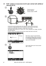
3.6
Earth resistance measurement with 3-pole method with ERP-1
adapter (R
E
3P+ERP-1)
Turn the meter on.
Set the rotational
function selector at
3P
.
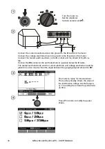
The current electrode (driven into earth) should be connected to
H
socket of the meter.
The voltage electrode (driven into earth) should be connected to
S
socket of the meter.
The tested leg of the pole should be connected to
E
socket of the meter with the lead.
The tested leg of the pole, the current electrode and the voltage electrode should be arranged in one
line.
Clamps should be attached to the tested leg of the pole below the connection point of
E
lead.


