MRU-200
● MRU-200-GPS – USER MANUAL
33
3.8
Earth impedance measurement with impulse method (R
E
4P )
The impulse method is applied in the case of measurement of the dynamic impedance of light-
ning arrester earthing systems. It must not be used for the purpose of measurements of protective
and working earthing systems.
Due to the high steepness of the test pulse leading edge the inductivity of the earth electrode
highly influences its impedance. Therefore the impedance of the earth electrode measured by means
of the impulse method depends upon its length and the steepness of the test pulse leading edge.
The inductivity of the earth electrode causes a shift between the current spikes and the resultant
voltage drop. Hence extensive earth electrodes of a low resistance measured by means of the low-
frequency method may have a much higher value of the dynamic impedance.
The impulse impedance is calculated on the basis of the following formula:
S
S
E
I
U
Z
Where U
S
, I
S
– peak value of the current and voltage.
The impulse method is used to determine the resultant earth impedance. Therefore the control
measurement points must not be undone.
It is recommended to place the test leads in such a manner that the angle between them is at
least 60°.
Note:
Measuring leads must be completely unrolled. Otherwise the result of the
measure may be wrong.
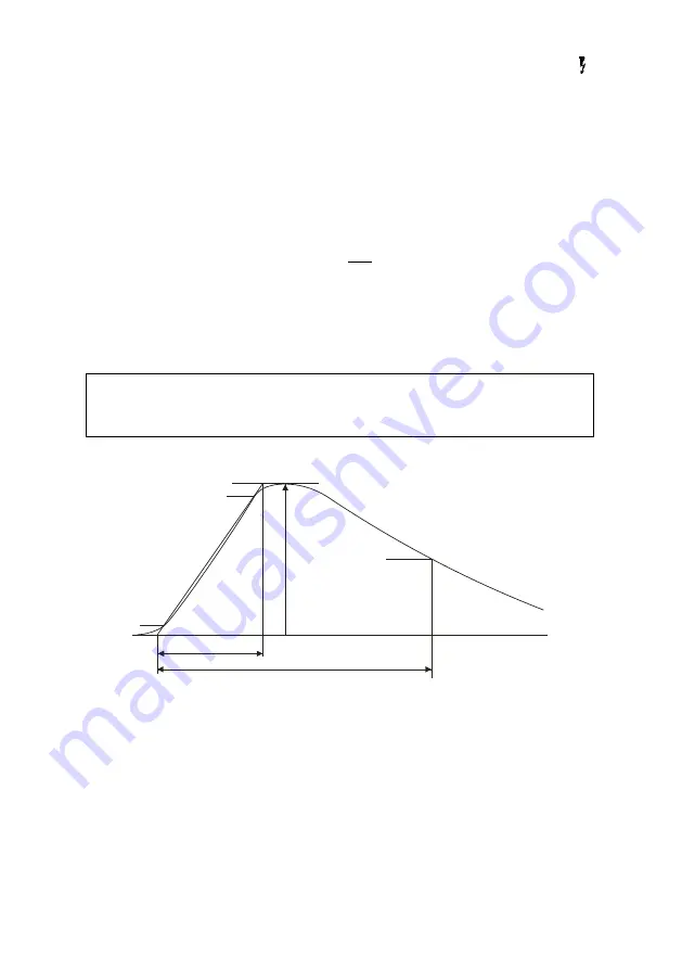
The following illustration explains the numbers which determine the shape of the pulse (in ac-
cordance with EN 62305-1 Lightning protection
– Section 1. General Requirements).
10%
90%
50%
T
1
T
2
t
t = current amplitude
T
1
= pulse leading edge duration
T
2
= time to semi-spike
The pulse shape is determined by the relation T
1
/T
2
eg: 4/10
μs.


