background image

MZC-304 

– USER MANUAL 

25 


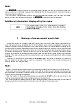
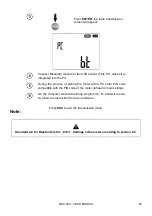
Press 

ENTER

, the radio transmission 

screen will appear. 


Connect Bluetooth module to the USB socket of the PC, unless it is 
integrated into the PC. 


During  the  process  of  pairing  the  meter  with  a  PC  enter  PIN  code 
compatible with the PIN code of the meter defined in main settings. 


On the computer start data storing programme. To transmit the da-
ta, follow the instruction from your software. 


Press 

ESC

 to exit the transmission mode. 

Note: 


Standard pin for Bluetooth is the „0123”. Settings in the meter according to section 2.2. 


Summary of Contents for MZC-304

Page 1: ......

Page 2: ......

Page 3: ...USER MANUAL FAULT LOOP IMPEDANCE METER MZC 304 SONEL S A Wokulskiego 11 58 100 widnica Version 2 04 03 04 2019...

Page 4: ...current measurement of resistance 16 2 9 3 Compensation of test leads resistance autozeroing 17 3 Memory of measurement result data 18 3 1 Storing the measurement result data in the memory 19 3 2 Cha...

Page 5: ...a damaged meter which is completely or partially out of order leads with damaged insulation a meter which ahs been stored to long in unsuitable conditions for example is wet When the meter is transfe...

Page 6: ...nd pose a threat to the user 2 1 Turning the meter on and off display backlight Briefly press the button to turn on the meter Press it for a longer time to turn it off is displayed Press briefly the b...

Page 7: ...settings see section 3 5 2 Data Transmission For software update proceed according to point 3 5 1 New software may be downloaded from www sonel pl 2 3 Remembering the last measurement result Result of...

Page 8: ...ved The person making a measurement must ensure that he she is standing on a non insulated floor during the measurement otherwise the result of the measurement may be incorrect The threshold value whi...

Page 9: ...tive and their results are unreliable This is due to the instability of internal impedance in in verter circuits during its operation The measurements of fault loop impedance should not be performed d...

Page 10: ...rated voltage for the short circuit current calculation In such a case horizontal dashes will be displayed instead a short circuit current value The following diagram shows voltage ranges for which sh...

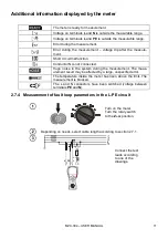
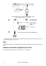
Page 11: ...meas urement in the L L circuit The meter is ready for measurement Phase conductor length or the or symbol UL N or UL L voltage Make the measurement by pressing the START button Read the main meas ure...

Page 12: ...n many measurements are made at short time intervals the meter may emit a large amount of heat As a result of this the enclosure of the device may become hot This is normal and the meter is equipped w...

Page 13: ...N is not connected Huge noise in the system during the measurement The meas urement result may be affected by a large unspecified error The temperature inside the meter has risen above the limit The m...

Page 14: ...E voltage Make measurement by pressing the START button Remaining issues connected with the measurements are the same as those described for meas urements in L N circuit or L L circuit Note Double lea...

Page 15: ...easurement parameters according to section 2 7 1 Connect the test leads according to one of the drawings Remaining issues connected with the measurements are the same as those described for meas ureme...

Page 16: ...sly use the phase of the same system as a secondary source of current disconnect the PE and N conductors from the measured earth electrode see figure below Otherwise the meter will measure an incorrec...

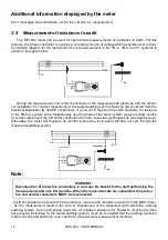
Page 17: ...h 200 mA current Turn on the meter Turn the rotary switch to the RCONT position The meter is ready for measurement RX N L Connect test leads according to the draw ing Activate the measurement by press...

Page 18: ...th conductors Huge noise in the system during the measurement The measurement result may be affected by a large unspeci fied error Measuring range is exceeded 2 9 2 Low current measurement of resistan...

Page 19: ...ement result may be affected by a large unspeci fied error Measuring range is exceeded 2 9 3 Compensation of test leads resistance autozeroing Turn on the meter Turn the rotary switch to the RCONT or...

Page 20: ...y cell marked with a selected number and in a selected memory bank Thanks to this the user of the meter can at his her discretion assign memory cell numbers to individual measurement points and the me...

Page 21: ...ment The meter is in the memory stor ing mode Cell is empty The cell contains the result of the same type which is to be entered The cell contains the measurement results of the displayed types The ce...

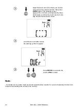
Page 22: ...t accompanied by three short beeps and then the meter returns to dis play the last measurement result An attempt to overwrite causes the warning symbol to appear Press ENTER to overwrite the result or...

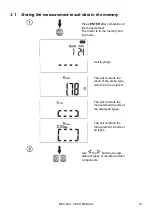
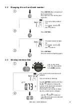
Page 23: ...d buttons Press SET SEL The cell number is flashing again 3 3 Viewing memory data Turn on the meter Turn the rotary switch to the MEM position The content of the last saved cell appears The cell numbe...

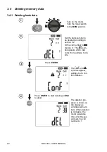
Page 24: ...ction 3 2 St the cell number to before 1 The sym bol appears which indi cates the readiness to de lete Press ENTER The and symbols appear asking you to con firm deletion Press ENTER to start deleting...

Page 25: ...e symbol appears which indi cates the readiness to de lete Press ENTER The and symbols appear asking you to con firm deletion Press ENTER to start deleting or ESC to abort The deletion pro gress is sh...

Page 26: ...supplied with the meter Information on the availability of other programs cooperating with the meter may be obtained from the manufacturer or its authorized distributors The software may be used for...

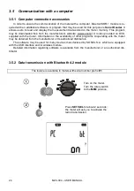
Page 27: ...ing the process of pairing the meter with a PC enter PIN code compatible with the PIN code of the meter defined in main settings On the computer start data storing programme To transmit the da ta foll...

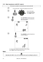
Page 28: ...on the meter Turn the rotary switch to the MEM position Press SET SEL for about 2 seconds the meter will ask you to activate the radio transmission Press ENTER the radio transmission screen will appe...

Page 29: ...No acclimatization Do not perform the meas urements until the meter reaches the ambient tem perature about 30 minutes and dries Fault loop Sucessive results ob tained in the same measuring point are s...

Page 30: ...rtment at the bottom of the enclosure WARNING Before replacing the batteries disconnect the test leads from the meter To replace the batteries 1 Disconnect the leads from the measuring circuit and tur...

Page 31: ...a while even unused batteries Modern fast chargers detect too low and too high temperature of the batteries and respond accord ingly If the temperature is too low the charging process should not star...

Page 32: ...and Electronic Equipment Act Before sending the instrument to the collection point do not dismantle any parts by yourself Observe local regulations on disposal of packagings and used batteries 9 Techn...

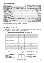
Page 33: ...001 A Calculated on the basis of uncertainty for fault loop 2 00 19 99A 0 01 A 20 0 199 9A 0 1 A 200 1999A 1 A 2 00 19 99kA 0 01 kA 20 0 40 0kA 0 1 kA Prospective fault current calculated and displaye...

Page 34: ...splayed value of the impedance because the meter calculates the current from unrounded value of fault loop impedance which is used for displaying As the correct value consider Ik current value display...

Page 35: ...acturing are ISO 9001 compliant s the device meets the requirements of the IEC 61557 standard t the product meets the EMC requirements immunity for industrial environment according to the following st...

Page 36: ...socket CAT II 1000V 2 pcs rad WASONREOGB1 and blue WASONBUOGB1 rigid hanger with a hook WAPOZUCH1 carrying case for the meter and accessories WAFUTM6 meter harness WAPOZSZE4 SONEL CD user manual warra...

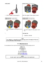
Page 37: ...version AGT 32P adapter for three phase sock ets LSWPLMZC304 calibration certificate Note The software is supported by the following systems Windows XP Service Pack 2 Windows Vista Windows 7 11 Manuf...

Page 38: ...ters o thermal imagers o luxmeters The Calibration Certificate is a document that presents a relation between the calibration standard of known accuracy and meter indications with associated measureme...

Page 39: ......

Page 40: ......

Reviews: