MZC-304
– USER MANUAL
32
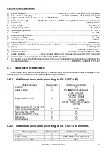
Fault loop resistance R
S
and fault loop reactance X
S
Display range
Resolution
Measurement uncertainty
0.00..19.99
0.01
(6% + 10 digits) of Z
S
value
20.0..199.9
0.1
(6% + 5 digits) of Z
S
value
Calculated and displayed for ZS<20
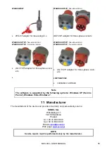
Short-circuit current I
K
Test range according to IEC 61557 can be calculated on the basis of test ranges Z
S
and rated voltag-
es.
Display range
Resolution
Measurement uncertainty
0.110
…1.999A
0.001 A
Calculated on the basis of
uncertainty for fault loop
2.00...19.99A
0.01 A
20.0...199.9A
0.1 A
200...1999A
1 A
2.00...19.99kA
0.01 kA
20.
0…24.0kA
0.1 kA
Prospective fault current calculated and displayed by the meter may slightly differ from the val-
ue calculated by the user with a calculator, basing on the displayed value of the impedance,
because the meter calculates the current from unrounded value of fault loop impedance (which
is used for displaying). As the correct value, consider I
k
current value, displayed by the meter or
by firmware.
Low-voltage continuity and resistance measurement
Measurement of continuity of protective conductors and equipotential bondings with
200 mA
current
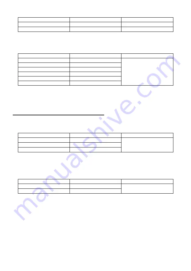
Measurement range according to IEC 61557-4:
Range
Resolution
Measurement uncertainty
0.00...19.99
0.01
(2% m.v. + 3 digits)
20.0...199.9
0.1
200...400
1
Voltage at open terminals: 4…9V
Output current at R<2
: min 200mA (I
SC
: 200...250mA)
Compensation of test leads resistance
Measurements for both current polarizations
Low-current resistance measurement
Range
Resolution
Measurement uncertainty
0.0...199.9
0.1
(3% m.v. + 3 digits)
200...1999
1
Voltage at open
terminals: 4…9V
Short-circuit current I
SC
: 8…15mA
Audio signal for measured resistance < 30
± 50%
Compensation of test leads resistance

