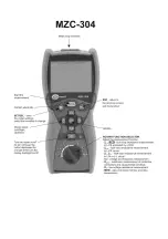
MZC-304
– USER MANUAL
14
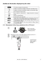
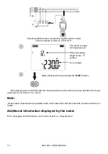
Additional information displayed by the meter
Error messages and information - as for the L-N and L-L measurement.
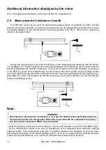
2.8 Measurement of resistance to earth
The MPI-502 meter can be used for approximate measurements of resistance to earth. For this
purpose, the phase conductor is used as a secondary source of voltage which generates test current.
Connection diagram for the instrument for such measurement in the TN-C, TN-S and TT systems is
shown in the figure below.
L
PE
N(PEN)
Ru
Rr
During the measurement, check the connections of the measured earth electrode with the electri-
cal installation. For correct measurement, the tested earthing systm should be disconnected from the
electrical installation (N and PE conductors). If you want to measure the earth electrode, for instance
in the TN-C-S system and simultaneously use the phase of the same system as a secondary source
of current, disconnect the PE and N conductors from the measured earth electrode (see figure below).
Otherwise, the meter will measure an incorrect value (the test current will flow not only through the
measured earthing system).
L
PE
N
Ru
Rr
L1
L1
L2
L3
PE
Disconnect
Note:
WARNING:
Disconnection of protective conductors is a serous life hazard for the staff performing the
measurements and also third parties. When the measurements are completed, the protec-
tive and neutral conductors MUST be reconnected.
- If it is not possible to disconnect the conductors, use an earth resistance meter from the MRU range.
- As the measurement result is the sum of impedances of the measured earth electrode, working
earthing system, source and phase conductor, it contains a positive error. However, if such error does
not exceed a limit value for the tested earthing system, it can be concluded that the earthing has been
made correctly and and there is no need for a more accurate measurement methods.

