2 Operation of the analyzer
15
2 Operation of the analyzer
2.1
Buttons
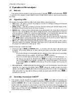
The keyboard of the analyzer consists of two buttons: ON/OFF
and START/STOP
. To switch-on the analyzer, press ON/OFF button. START/STOP button is used to start and stop
recording.
2.2
Signalling LEDs
The analyzer is equipped with five LEDs that indicate different operating states:
ON
(green)
– the LED is on when the analyzer is turned on. During recording with activated
sleep mode, the LED is off.
LOGG
(yellow)
– indicates recording in process. During recording with activated sleep mode,
the LED is off and it is switched on in 10-sec. intervals
ERROR
(red)
– blinking of this LED indicates a potential problem with connecting to the tested
network or the incompatibility of the active configuration with network parameters. Control cri-
teria are defined in chapter 2.6. Continuous light indicates one of the possible internal errors
of the analyzer (see also the description of additional statuses presented below).
MEM
(red)
– when this LED is on, it indicates that the data cannot be recorded on the memory
card.
MEM
LED is continuously lit when the entire space on the memory card is filled. See
also the description of additional statuses presented below.
BATT
(red) - battery status. Blinking indicates that the battery is low (charged in 20% or less).
When the battery is completely discharged, LED lights up for 5 seconds (with beep) and then
the analyzer is switched off in emergency mode.
Additional statuses indicated by LEDs:
Continuous light of
MEM
and
ERROR
LEDs
– no memory card, the card is damaged or not
formatted. When these LEDs are on after inserting a memory card, there are two possible
scenarios:
o
the card is damaged or incompatible with the analyzer. In this case there is no possibility
of further work with the analyzer. START button
is inactive.
o
the card is not formatted (missing files required by the analyzer or files damaged)
– in
this case you can press the START button
(it is active), which will start the pro-
cess of formatting the card (NOTE: all data on the card will be deleted). If the process
is successful
MEM
and
ERROR
LEDs will go off and the analyzer will be ready for
further work.
Blinking
ON
LED
– FIRMWARE.PQF file detected on the card, containing the correct firmware
update file. You may press the START button
to begin the update process. During the
update process
ON
and
MEM
LEDs blink simultaneously. After this process is completed, the
meter will restart. You may skip the firmware update by pressing the ON/OFF button
or
by waiting 10 seconds.
2.3
Switching the analyzer ON/OFF
The analyzer may be switched-on by pressing button
. Green
ON
LED indicates that
analyzer is switched on. Then, the analyzer performs a self-test and when an internal fault is
detected,
ERROR
LED is lit and a long beep (3 seconds) is emitted
– measurements are
blocked. After the self-test, the meter begins to test if the connected mains configuration is the
same as the configuration in analyzer’s memory, and when an error is detected
ERROR
LED
flashes every 0.5 seconds. When
ERROR
LED flashes the analyzer still operates as normal
and measurements are possible.
Summary of Contents for PQM-700
Page 85: ...85 Notes...


