2 Operation of the analyzer
17
USB is an interface that is continuously active and there is no way to disable it. To connect the
analyzer, connect USB cable to your PC (USB slot in the device is located on the left side and is
secured with a sealing cap). Before connecting the device, install
Sonel Analysis
software with the
drivers on the computer. Transmission speed is 921.6 kbit/s.
2.6
Indication of connection error
During operation, the analyzer continuously monitors the measured parameters for compliance
with the current configuration. Basing on several criteria listed below, the analyzer controls the light-
ing of
ERROR
LED. If the analyzer does not detect any inconsistency, this LED remains off. When
at least one of the criteria indicates a potential problem,
ERROR
LED starts to blink.
The criteria used by the analyzer for detecting a connection error are as follows:
deviation of RMS voltage exceeding ±15% of nominal value,
deviation of the phase angle of the voltage fundamental component exceeding ±30
of the the-
oretical value with resistive load and symmetrical mains (see note below)
deviation of the phase angle of the current fundamental component exceeding ±55
of the the-
oretical value with resistive load and symmetrical mains (see note below)
network frequency deviation exceeding ±10% of the nominal frequency.
2.7
Warning about too high voltage or current
During its operation, the analyzer monitors continuously the value of voltages and currents con-
nected to the measuring inputs. If the voltage of any active phase exceeds approx. 20% of the
nominal voltage (> 120% U
NOM
) set in the measurement configuration, a two-tone continuous beep
is activated. The same applies for currents
– an alarm signal is activated if the measured current in
any of the active channels exceeds 20% of nominal current (range of clamps; >120% I
NOM
). In such
a situation, check whether the voltage and current in the measured network is within voltage and
current limits allowable for the analyzer or check if the analyzer configuration is correct and change
it, if necessary.
Notes
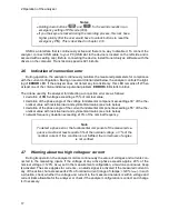
Holding down buttons
and
for 5 seconds results in an
emergency setting of PIN code (000).
If you the keys are locked during the recording process, this lock has a
higher priority (first the user would have to unlock buttons to reset the
emergency PIN). This is described in chapter 2.10.
Note
To detect a phase error, the fundamental component of the measured se-
quence must be at least equal to 5% of the nominal voltage, or 1% of the
nominal current. If this condition is not fulfilled, the correctness of angles
is not verified.
Summary of Contents for PQM-700
Page 85: ...85 Notes...


