4 Design and measurement methods
27
4 Design and measurement methods
4.1
Voltage Inputs
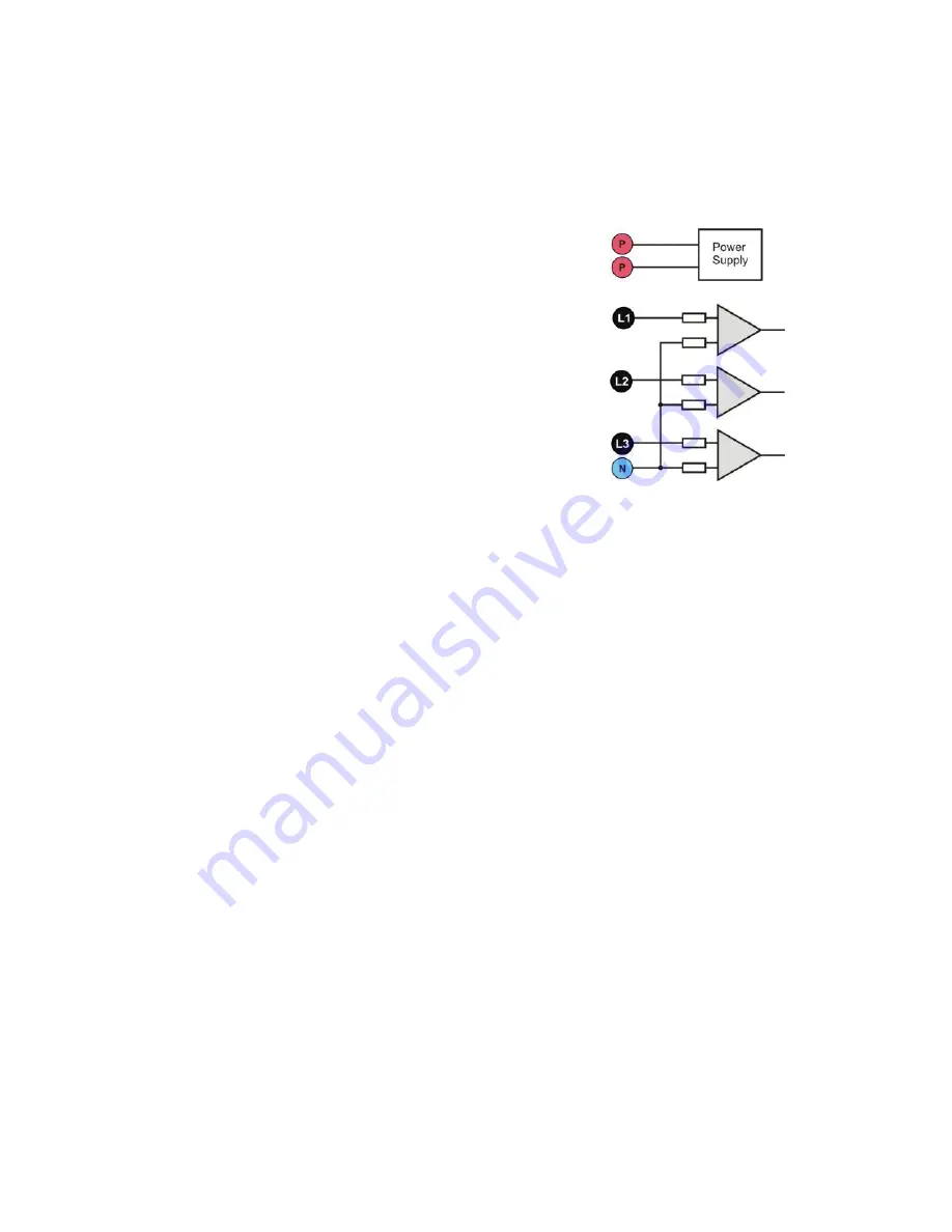
The voltage input block is shown in Fig. 14. Three phase inputs L1/A, L2/B, L3/C have common
reference line, which is the N (neutral) input. Such inputs configuration allows reducing the number
of conductors necessary to connect the analyzer to the measured mains. Fig. 14 presents that the
power supply circuit of the analyzer is independent of the meas-
uring circuit. The power adapter has a nominal input voltage
range 100...415 V AC
(140…415 V DC) and has a separate
terminals.
The analyzer has one voltage range, with voltage range
±1150V.
4.2
Current inputs
The analyzer has four independent current inputs with iden-
tical parameters. Current transformer (CT) clamps with voltage
output in a 1 V standard, or flexible clamps (probes) F-1(A), F-
2(A) and F-3(A) can be connected to each input.
A typical situation is using flexible clamps with built-in elec-
tronic integrator. However, the PQM-700 allows connecting the
Rogowski coil alone to the input and a digital signal integration.
4.2.1 Digital integrator
The PQM-700 uses the solution with digital integration of signal coming directly from the
Rogowski coil. Such approach has allowed the elimination of the analog integrator problems con-
nected with the necessity to ensure declared long-term accuracy in difficult measuring environ-
ments. The analog integrators must also include the systems protecting the inputs from saturation
in case DC voltage is present on the input.
A perfect integrator has an infinite amplification for DC signals which falls with the rate of
20 dB/decade of frequency. The phase shift is fixed over the whole frequency range and equals -
90°.
Theoretically infinite amplification for a DC signal, if present on the integrator input, causes the
input saturation near the power supply voltage and makes further operation impossible. In practi-
cally implemented systems, a solution is applied which limits the amplification for DC to a specified
value, and in addition periodically zeroes the output. There are also techniques of active cancella-
tion of DC voltage which involve its measurement and re-applying to the input, but with an opposite
sign, which effectively cancels such voltage. There is a term “leaky integrator” which describes an
integrator with finite DC gain. An analog leaky integrator is just an integrator featuring a capacitor
shunted with a high-value resistor. Such a system is then identical with a low-pass filter of a very
low pass frequency.
Digital integrator implementation ensures excellent long-term parameters
– the entire procedure
is performed by means of calculations, and aging of components, drifts, etc. have been eliminated.
However, just like in the analog version, also here we can find the saturation problem and without
a suitable counteraction the digital integration may become useless. It should be remembered that
both, input amplifiers and analog-to-digital converters, have a given finite and undesirable offset
which must be removed prior to integration. The PQM-700 analyzer firmware includes a digital filter
which is to remove totally the DC voltage component. The filtered signal is subjected to digital inte-
gration. The resultant phase response has excellent properties, and the phase shift for most critical
frequencies 50 and 60 Hz is minimal.
Ensuring the least possible phase shift between the voltage and current components is very
important for obtaining small power measurement errors. It can be proven that approximate power
Fig. 14. Voltage Inputs
and integrated AC power
adapter.
Summary of Contents for PQM-700
Page 85: ...85 Notes...


