PQM-700 Operating Manual
44
6.2
Current measurement
6.2.1 Current transformer clamps (CT) for AC measurements
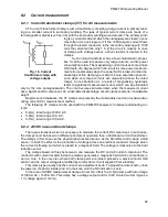
CT Current Transformer Clamp is just a transformer converting a large current in primary wind-
ing to a smaller current in secondary winding. The jaws of typical current clamp are made of a
ferromagnetic material (such as iron) with the secondary winding wound around. The primary wind-
ing is a conductor around which the clamp jaws are closed, hence
most often it is one single coil. If the 1000-ampere current flows
through the tested conductor, in the secondary winding with 1000
coils the current will be only 1 A (if the circuit is closed). In case
of clamps with voltage output, a shunt resistor is located in the
clamps.
Such current transformer has a few characteristic proper-
ties. It can be used to measure very large currents, and its power
consumption is low. The magnetizing current causes some phase
shift (tenth of a degree) which can result in some power measure-
ment error (particularly when the power factor is low). Another dis-
advantage of this clamp type is also the core saturation phenom-
enon when very large currents are measured (above the rated
range). Core saturation as a result of magnetizing hysteresis
leads to significant measurement errors which can be eliminated
only by the core demagnetization. The core becomes saturated also when the measured current
has a significant DC component. An undeniable disadvantage of such clamp is also its considerable
weight.
Despite such drawbacks, the CT clamps are presently the most widely used non-invasive alter-
nating current (AC) measurement method.
The following CT clamps can be used with the PQM-700 analyzers to measure alternating cur-
rents:
C-4(A), rated range 1000 A AC,
C-6(A), rated range 10 A AC,
C-7(A), rated range 100 A AC.
6.2.2 AC/DC measurement clamps
There are situations when it is necessary to measure the current DC component. In such case,
the clamps must be based on different principle of operation than a traditional current transformer.
The clamps in this case use the physical phenomenon known as the Hall effect and include a Hall
sensor. In brief: the effect is the production of voltage across an electrical conductor through which
the current is flowing and which is placed in a magnetic field. The voltage is transverse to the field
induction vector.
The clamps based on this phenomenon can measure the DC and AC current component. The
conductor with current located inside the clamps generates a magnetic field which concentrates in
an iron core. In the core slot, where both clamp parts are joined, placed is a semiconductor Hall
sensor, and its output voltage is amplified by an electronic circuit supplied from a battery.
This clamp type usually has the current zero adjustment knob. To adjust the current zero, close
the jaws (no conductor inside) and turn the knob until the DC indication is zero.
In the area of AC/DC measurement clamps, Sonel S.A. offers the C-5(A) clamp with rated range
of 1000 A AC / 1400 A DC. This clamp has a voltage output and for 1000 A rated current it gives a
1 V voltage signal (1 mV/A).
Fig. 16. Current
transformer clamp with
voltage output.
Summary of Contents for PQM-700
Page 85: ...85 Notes...

