PQM-700 Operating Manual
50
This component explains the situation in which an unbalanced three-phase load of a purely resistive
character results in the power factor less than one. Such load does not have the reactive power
Q
,
and still the results from the power triangle
S
,
P
,
Q
are totally different (the Budeanu’s power theory
with its distortion power could not explain this situation either
– in a purely resistive load, the distor-
tion power
D
B
equals zero).
An attempt to connect the IEEE 1459-
2000 standard with the Czarnecki’s power theory leads
to the conclusion that nonactive power conceals at least three separate physical phenomena which
influence the reduced effectiveness of energy transmission from the source to the receiver, i.e.
reduction of the power factor.
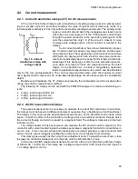
𝑃𝐹 =
𝑃
𝑆
𝑒
=
𝑃
√𝑃
2
+ 𝐷
𝑠
2
+ 𝑄
2
+ 𝐷
𝑢
2
In the IEEE 1459-2000 standard, reactive power known as Q has been limited to the fundamen-
tal component, for both one-phase and three-phase systems:
𝑄
1
= 𝑈
1
𝐼
1
sin 𝜑
1
In three-phase systems, only the positive sequence component is taken into consideration:
𝑄
1
+
= 3𝑈
1
+
𝐼
1
+
sin 𝜑
1
+
Correct measurement of this power requires the same phase rotation sequence (i.e. phase L2
delayed by 120
in relation to L1, phase L3 delayed by 240
in relation to L1).
The term of positive sequence component will be discussed in more detail in the section devoted
to unbalance.
The value of reactive power of the fundamental component is the main value which allows es-
timating the size of capacitor to improve the displacement power factor (DPF), that is the displace-
ment of the voltage fundamental components in relation to the current fundamental component (i.e.
compensator of the reactive power of the fundamental component).
6.4.3 Reactive power and three-wire systems
Correct reactive power measurement is impossible in unbalanced receivers connected accord-
ing to the three-wire system (delta and wye systems without the N conductor). Such statement may
come as a surprise for many people.
T
he receiver can be treated as a “black box” with only 3 terminals available. We cannot deter-
mine its internal structure. In order to calculate the reactive power, we need to know the phase shift
angle between the voltage and the current at each leg of such receiver. Unfortunately, we do not
know this angle. In the delta-type receiver we know the voltages on individual impedances, but we
do not know the current; in such systems, the phase-to-phase voltages and line currents are meas-
ured. Each line current is a sum of two phase currents. In the wye without N-type receivers, we
know the currents flowing through impedance, but we do not know the voltages (each phase-to-
phase voltage is a sum of two phase-to-neutral voltages.
We need to take account of the fact that at given voltage values at terminals and currents flowing
into such “black box”, there is an infinite number of variants of receiver internal structure which will
give us identical measurement results of voltage and current values visible outside the black box.
Then, how is it possible that there are reactive power meters intended for measurements in
three-wire systems and the mains analyzers which allow the reactive power measurement under
such circumstances?
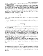
In both cases, the manufacturers use the trick which involves an artificial creation of a reference
point (virtual neutral terminal N). Such point can be created very easily by connecting to the termi-
nals of our black box a wye-connected system of three resistors of the same value.
In no case should a measuring instrument mislead the user, and such approximation can be
Summary of Contents for PQM-700
Page 85: ...85 Notes...


