PQM-700 Operating Manual
52
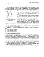
The higher the harmonics content, the higher difference in readings, and of course, as a con-
sequence, other fees for measured energy.
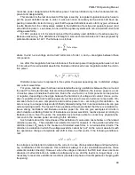
As it has been signaled before, the reactive power measurement in unbalanced three-wire sys-
tems with traditional meters is subject to an additional error caused by creation of a virtual zero
inside the meter which has little to do with actual zero of the receiver.
On top of that, the manufacturers usually do not give any information about the applied meas-
uring method.
One can only wait impatiently for the next version of the standard, which
– let’s hope – will
define the measuring and testing methods much more precisely, also for non-sinusoidal conditions.
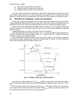
6.4.5 Apparent power
Apparent power S
is expressed as the product of RMS voltage and RMS current:
𝑆 = 𝑈𝐼
As such, the apparent power does not have a physical interpretation; it is used during designing
of transmission equipment. In terms of value, it is equal to maximum active power which can be
supplied to a load at given RMS voltage and current. Thus, the apparent power defines the maxi-
mum capacity of the source to supply usable energy to the receiver.
The measure of effective use of supplied power by the receiver is the power factor, which is the
ratio of active power to apparent power.
In sinusoidal systems:
𝑃𝐹 =
𝑃
𝑆
=
𝑈𝐼𝑐𝑜𝑠𝜑
𝑈𝐼
= 𝑐𝑜𝑠𝜑
In non-sinusoidal systems such simplification is however not allowed, and the power factor is
calculated on the basis of actual ratio of active power and apparent power.
𝑃𝐹 =
𝑃
𝑆
In one-phase systems, the apparent power is calculated as shown in the formula above and
there are no surprises. However, it turns out that in three-phase systems calculation of this power
is equally difficult as calculation of reactive power. Of course, this is related to actual systems with
non-sinusoidal waveforms which additionally can be unbalanced.
The tests have shown that the formulas used so far can give erroneous results if the system is
unbalanced. As apparent power is a conventional magnitude and does not have a physical inter-
pretation, determination which of proposed apparent power definitions is correct could be difficult.
Yet, the attempts have been made based on the observation that the apparent power is closely
related to the transmission losses and the power factor. Knowing the transmission losses and the
power factor, one can indirectly specify a correct definition of apparent power.
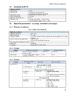
The definitions which have been used so far include arithmetic apparent power and vector ap-
parent power. The test have shown however that neither the arithmetic definition nor the vector
definition give correct value of the power factor. The only definition which did not fail in such a
situation, was the definition proposed as early as in 1922 by German physicist F. Buchholz:
𝑆
𝑒
= 3𝑈
𝑒
𝐼
𝑒
It is based on RMS current and voltage, and the power is called an effective apparent power
(hence, the index “e” in designations in three-phase systems). Those effective voltage and current
values are such theoretical values which represent voltage and current in an energetically equiva-
lent three-phase balanced system. Consequently, the key issue is to determine the
U
e
and
I
e
.
Summary of Contents for PQM-700
Page 85: ...85 Notes...


