6 Power Quality - a guide
57
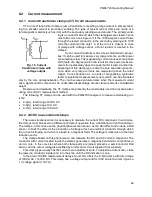
unbalance, there are non-zero positive and negative sequence components. The measure of such
unbalance is so-called unbalance factors. And this is due to this unbalance of the fundamental
component and additionally the differences in amplitudes and phases of the higher harmonics, that
also these harmonics will have the positive, negative and zero sequence components. The larger
the unbalance, the higher the content of remaining components.
6.5.2 THD
Total Harmonic Distortion (THD) is the most widely used measure of waveform distortion. Two
versions of this factor are applied in practical use:
THD
F
(THD-F or simply THD)
– total harmonic distortion referred to the fundamental com-
ponent,
THD
R
(THD-R)
– total harmonic distortion referred to the RMS value.
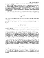
In both cases, THD is expressed in percent. The definitions are given below:
𝑇𝐻𝐷
𝐹
=
√∑
𝐴
ℎ
2
𝑛
ℎ=2
𝐴
1
× 100%
𝑇𝐻𝐷
𝑅
=
√∑
𝐴
ℎ
2
𝑛
ℎ=2
𝐴
𝑅𝑀𝑆
× 100%
where: A
h
– RMS of the
h
th order harmonics,
A
1
– RMS of the fundamental component,
A
RMS
– RMS waveform.
Limitation of the number of harmonics used to calculate THD is conventional and is caused
mainly by measuring limitations of the device. Because the PQM-700 is capable of measuring the
harmonic components up to the 40
th
order, the harmonics up to the 40
th
order are used to calculate
THD.
Please note that when the waveforms are very distorted, the two definitions presented above
will give significantly different results. THD
R
may not exceed 100%, but there is no such limit for
THD
F
and it may go up to 200% or higher. Such case can be seen when measuring very distorted
current. The voltage harmonic distortion usually does not exceed a few percent (both THD
F
and
THD
R
); for example, the limit according to EN 50160 is 8% (THD
F
).
6.6
Unbalance
Unbalance is term related to three-phase systems and can refer to:
supply voltage unbalance
load current unbalance
receiver unbalance
In three-phase systems, the voltage (current) unbalance occurs when values of three compo-
nent voltages (currents) are different and/or the angles between individual phases are not equal to
120
.
The receiver unbalance occurs when impedance values of individual receiver branches are not
equal.
These phenomena are particularly dangerous for three-phase motors, in which even a slight
voltage unbalance can cause current unbalance that is many times larger. In such situation, the
motor torque is reduced, heat losses in windings increase, and mechanical wear is faster. The un-
balance also has an unfavorable effect on power supply transformers.
The most frequent reason of unbalance is uneven load on individual phases. A good example
is connecting to three-phase systems of large one-phase loads, such as railway traction motors.
The PQM-700 is capable of measuring the voltage and current unbalance with a symmetrical
components method. This method is based on the assumption that each set of three unbalanced
Summary of Contents for PQM-700
Page 85: ...85 Notes...


