7 Technical specifications
71
Distortion power D / Apparent dis-
tortion power S
N
(min, max)
Depending on the con-
figuration
Basing on 10/12-period value
Power Factor PF (min, max)
0…1
Basing on 10/12-period value
Displacement power factor cosφ/
DPF (min, max)
0…1
Basing on 10/12-period value
tanφ (min, max)
0…10
Basing on 10/12-period value
Active energy E
P
(max)
Depending on the con-
figuration
Exceedance checked every 10/12 periods
(for consumed and supplied energy)
Reactive energy E
Q
(max)
Depending on the con-
figuration
Exceedance checked every 10/12 periods
(for consumed and supplied energy)
Apparent energy E
S
(max)
Depending on the con-
figuration
Exceedance checked every 10/12 periods
Total harmonic distortion for volt-
age THD-F (max)
0…100%
Basing on 10/12-period value
Total harmonic distortion for cur-
rent THD-F (max)
0…200%
Basing on 10/12-period value
Voltage harmonic amplitudes
(max)
0 ... 100% or absolute
values
Basing on 10/12-period value;
Independent thresholds for all harmonics
in the range of 2 ... 40
Current harmonic amplitudes
(max)
0…200% or absolute
values
Basing on 10/12-period value;
Independent thresholds for all harmonics
in the range of 2 ... 40
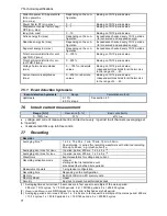
7.5.1 Event detection hysteresis
Event detection hysteresis
Range
Calculation method
Hysteresis
0..10%
in 0.1% steps
See section 4.7.
7.6
Inrush current measurement
Range [A,%]
Resolution [A, %]
Basic uncertainty
0…100% I
nom
0.1%
±1% I
nom
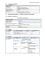
voltage and current measurement is carried out every ½ period in all channels (averaging set
to ½ period)
measurement time up to 60 seconds.
7.7
Recording
Recorder
Averaging time
(1)
1 s, 3 s, 10 s, 30 s, 1 min, 10 min, 15 min, 30 min.
Special mode: ½ period (for recording waveforms with a limited recording
time up to 60 sec, e.g. inrush current)
(2)
Averaging min / max for U
RMS
½ period, period, 200 ms, 1 s, 3 s, 5 s
(3)
Averaging min / max for I
RMS
½ period, period, 200 ms, 1 s, 3 s, 5 s
(3)
Waveforms
Event waveforms for voltage and current
Recording activation mode
manual
starting at the first detected event
scheduled (four defined time periods)
Measurement points
1, single user configuration
Recording time
Depending on the configuration
Memory
Built-in 2 GB micro-SD memory card
Memory Model
Linear
Security
Key lock to prevent unauthorized access
(1) Averaging times shorter than 10 seconds are in fact equal to a multiple of the mains period:
200 ms = 10/12 cycles, 1 s = 50/60 periods, 3 s = 150/180 periods, 5 s = 250/300 cycles.
(2) U
RMS(1/2)
and I
RMS(1/2)
are RMS values for one period, refreshed every half period.
(3) Averaging periods min./max. 200 ms, 1 s, 3 s, 5s are in fact equal to a multiple of the mains period: 200 ms
= 10/12 cycles, 1 s = 50/60 periods, 3 s = 150/180 periods, 5 s = 250/300 cycles
Summary of Contents for PQM-700
Page 85: ...85 Notes...


