PQM-700 Operating Manual
82
Frequency
Basic
uncertainty
Phase error
45…65 Hz
±0,5% ±0.1 mV
2
40
Hz…1 kHz
±1.0% ±0.2mV
unspecified
ratio:
5mV AC/1 A AC
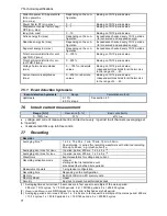
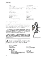
output impedance
11
type of insulation:
double, according to IEC 61010-1
measurement category according to IEC 61010-1:
III 300 V,
dimensions:
100
× 60 × 26 mm
weight:
approx. 160 g
maximum diameter of tested cable:
24 mm
length of probe cables:
1.5 m
operating temperature:
0
C…+50
C
relative humidity:
85% (non-condensing)
electromagnetic compatibility:
IEC 61326
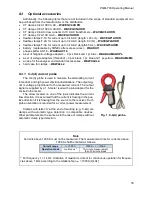
8.3.5 F-1(A), F-2(A), F-3(A) current probes
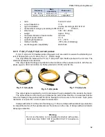
F-1(A), F-2(A) and F-3 flexible probes (Rogowski coil) are used to measure the alternating cur-
rent of frequencies up to 10 kHz in the 1
A…3000 A range.
The only difference between the F-1(A), F-2(A) and F-3(A) flexible probes is the coil size. The
electrical parameters are identical.
The output signal if voltage proportional to the derivative of the measured current, with the sen-
sitivity equal to 38.83 mV/1000 A for 50 Hz and 46.6 mV/1000 A for 60 Hz.
Fig. 5. F-1(A) probe
Fig. 6. F-2(A) probe
Fig. 7. F-3(A) probe
The output signal is supplied by a 2.2-meter lead with a pin adapted for the socket in the meter.
The arrow located on the closing unit indicates the current flow direction. It is assumed that the
current is flowing in the positive direction if it is flowing from the source to the receiver. Such probe
orientation is required for a correct power measurement.
Clamps with letter 'A' at the end of marking (e.g. F-3A) are clamps with automatic type detection
in compatible devices. Other parameters are the same as in the case of clamps without automatic
clamp type detection.
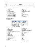
Warning
Do not use the device on non-insulated conductors with a poten-
tial of more than 1000 V CAT III and 600 V CAT IV in relation to
earth.
Summary of Contents for PQM-700
Page 85: ...85 Notes...


