TDR-410 OPERATING MANUAL version 1.03
9
Note:
After disconnecting the TDR-410 the current parameter settings are stored, including the re-
cently selected values Vp propagation factor and impedance Z.
This feature of the device is particularly advantageous in situations where multiple tests are per-
formed on the same type of cables.
4 Using the TDR-410
Upon completion of the set up procedures in section 3, press
ESC
to return to start up display and
select
TDR
(pressing the cursor
), or press
START
.
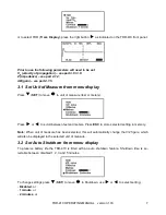
The following screen will be displayed:
1.
Vp setting
2.
Impedance setting (Z)
3.
Manual / Auto Fault Location
4.
Range scale
5.
Battery condition indicator
6.
Scan hold icon
7.
User variable gain (by user or auto)
8.
Cursor distance reading
9.
Cursor
10. Output pulse
4.1 Setting the fault location
You can set all the necessary parameters of the cable fault location from
Trace Display
:
Velocity of Propagation
Impedance value (Z)
Auto or Manual location mode (AFL, MFL)
Range Scale
Gain
To set a parameter, press the
SET
button (
). Until the parameter is highlighted, use
or
to
change the value or the option.
Summary of Contents for TDR-410
Page 1: ......
Page 2: ......
Page 6: ...TDR 410 OPERATING MANUAL version 1 03 4 15 ACCESSORIES 19 16 MANUFACTURER 19...
Page 22: ...TDR 410 OPERATING MANUAL version 1 03 20 NOTES...
Page 23: ......
Page 24: ......


