TDR-410 OPERATING MANUAL version 1.03
12
Coaxial Cable:
Connect the red clip to the centre wire and the black clip to the shield/screen.
Shielded Cable:
Connect the red clip to a wire adjacent to the shield and the black clip to the shield.
Twisted Pair:
Separate out one pair and connect the red and black clips to the two wires of the pair.
MulticoreCable:
Connect the clips to any two wires.
6 Cable Fault Location
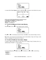
Having followed the set up procedures in the preceding sections, a typical display showing imped-
ance anomalies is shown below. Further examples are shown in section 12.
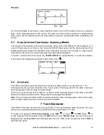
The vertical cursor line is moved left or right along the line of the trace by pressing
or
buttons
to determine the distance to the event. Position the cursor at the beginning of the event and read off
the distance at the bottom left corner.
Summary of Contents for TDR-410
Page 1: ......
Page 2: ......
Page 6: ...TDR 410 OPERATING MANUAL version 1 03 4 15 ACCESSORIES 19 16 MANUFACTURER 19...
Page 22: ...TDR 410 OPERATING MANUAL version 1 03 20 NOTES...
Page 23: ......
Page 24: ......


