background image

TDR-410 OPERATING MANUAL    version 1.03 

18 

14   Technical data 

Ranges Meters:  

7, 15, 30, 60, 120, 250, 500, 1km, 2km, 3km, 4km 

Ranges Feet 

20, 45, 90, 180, 360, 750, 1500, 3000, 6000, 10000, 14000. 

Range Selection  

Manual range control / Auto range 

Accuracy  

1% of selected range* 

Resolution  

Approx 1% of range 

Minimum cable lenght: 

4m (14ft) 

Sensitivity  

Min 3 pixel return at 4km on 0.6mm Ø, PE, TP 

Velocity Factor  

Adjustable from 1% to 99% 

Output Pulse  

5 volts peak to peak into open circuit 

Output Impedance  

Selectable 25, 50, 75 & 100 

Ω  

Output Pulse  

Width 3 ns to 3 

µs, Automatic with range 

Scan Rate  

2 scans/second or scan held, pre set for each range scale 

Tone Generator  

810 

– 1100Hz 

Battery Life  

30 hours continuous scanning 

Power Supply  

6 volts 4 x 1.5 AA Alkaline cells, on-screen low voltage indicator  

Power Down Selectable  

1, 2, 3, 5 minutes or disabled 

Back Lit Display  

128 x 64 pixel 

Operating Temp  

-

10º / 50ºC 

Storage Temp  

-

20º +70° C 

Dimensions  

165 x 90 x 37 mm (6.5 x 3.5 x 1.5 ins) 

Weight  

350 g (12oz) 

EMC  

BS/EN 61326-1 

Water/Dust Proof  

IP54 


Symbol complies with the current EU directives 

 
* Measurement accuracy of <+/- 1% assumes the instrument setting for velocity of propagation (Vp) 
of the cable under test to be accurately set, homogeneity of the Vp along the cable length, and accu-
rate cursor positioning. 


Summary of Contents for TDR-410

Page 1: ......

Page 2: ......

Page 3: ...TDR 410 OPERATING MANUAL version 1 03 1 OPERATING MANUAL TDR 410 TDR CABLE FAULT LOCATOR SONEL S A Wokulskiego 11 58 100 widnica Poland Version 1 03 08 09 2017...

Page 4: ...having purchased our measuring instrument TDR 410 is a modern measuring device which is easy and safe to use Please acquaint yourself with the present manual in order to avoid measuring errors and pr...

Page 5: ...410 9 4 1 SETTING THE FAULT LOCATION 9 4 1 1 Setting Velocity of Propagation Vp 10 4 1 2 Value Impedance Setting Z 10 4 1 3 Auto Fault Location and Manual Fault Location 10 4 1 4 Selecting range scale...

Page 6: ...TDR 410 OPERATING MANUAL version 1 03 4 15 ACCESSORIES 19 16 MANUFACTURER 19...

Page 7: ...ted conduc tors The TDR 410 has impedance matched circuits for 25 50 75 and 100 ohms and with velocity of propagation settings from 1 99 or the equivalent in feet or meters micro second will cover the...

Page 8: ...tinuity in the studied area based on Vp values select ed by a user and and measured the course time of the pulse 3 Preparing the TDR 410 for use Press button to power the tester the following screen w...

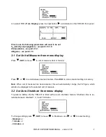
Page 9: ...measure feet or meters Press or to scroll between feet and meters Press ESC to store selected setting in memory Note When unit of measure has been selected this will automatically change the V 2 figu...

Page 10: ...ting selected in section 3 1 Press SET to move to displayed unit press to scroll between V 2 m s or Vp Vc To change the value of the V 2 or Vp factor go one level down press SET button so that the ind...

Page 11: ...splay and select TDR pressing the cursor or press START The following screen will be displayed 1 Vp setting 2 Impedance setting Z 3 Manual Auto Fault Location 4 Range scale 5 Battery condition indicat...

Page 12: ...s ESC to store set tings 4 1 3 Auto Fault Location and Manual Fault Location The TDR 410 may be used in auto or manual fault location modes Use SET button to scroll to displayed setting AFL or MFL use...

Page 13: ...and exit press ESC Note Manual measurement range change is just for MFL mode 4 1 5 Gain settings The TDR 410 has pre set gain for each of its 11 range scales there is in addition to this a user con tr...

Page 14: ...to the two wires of the pair MulticoreCable Connect the clips to any two wires 6 Cable Fault Location Having followed the set up procedures in the preceding sections a typical display showing imped an...

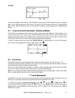
Page 15: ...at the bottom right hand corner 6 2 Accuracy The TDR 410 is able to measure distances to faults and cable lengths to an accuracy of 1 This measurement accuracy is based on the correct value of Vp bei...

Page 16: ...refit the battery compartment cover and refit the two screws 9 Cleaning and maintenance NOTE Apply solely the maintenance methods specified by the manufacturer in this manual The casing of the meter...

Page 17: ...ectric and electronic equipment Before the equipment is sent to a collection point do not dismantle any elements Observe the local regulations concerning disposal of packages worn out batteries and ac...

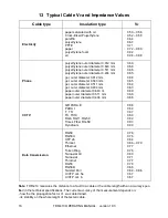
Page 18: ...er diameter 0 643 m paper outer diameter 0 511 mm paper outer diameter 0 404 mm 0 69 0 68 0 66 0 65 0 68 0 65 0 64 0 63 0 69 0 68 0 66 CCTV QR PARA III PARA I T TR TX TX10 RG6 RG11 RG59 Times Fiber RG...

Page 19: ...factor for different cable types are only an indication for the user to make swift and calculate the measurement with reasonable accuracy The use of VP allows the highest measurement accuracy calcula...

Page 20: ...Automatic with range Scan Rate 2 scans second or scan held pre set for each range scale Tone Generator 810 1100Hz Battery Life 30 hours continuous scanning Power Supply 6 volts 4 x 1 5 AA Alkaline cel...

Page 21: ...ser manual It is possible to additionally purchase from the manufacturer and distributors the following elements which are not included within the standard accessories voltage separator AS 2 WAADAAS2...

Page 22: ...TDR 410 OPERATING MANUAL version 1 03 20 NOTES...

Page 23: ......

Page 24: ......

Reviews: