background image

6

PAIRING

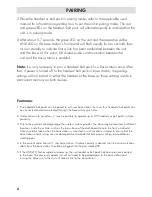
3. Place the headset or belt pack in pairing mode; refer to the applicable user’s 

manual for information regarding how to put the unit in pairing mode. The red 

and green LEDs on the headset / belt pack will alternate rapidly to indicate that the

unit is in pairing mode.

4. After about 5-7 seconds, the green LED on the unit and the respective yellow 

LINK LED on the base station’s front panel will flash rapidly for two seconds then 

turn on steadily to indicate that a link has been established between the unit 

and the base. At this point, full duplex audio communication between the 

unit and the base station is enabled.

Note:

It is only necessary to pair a headset / belt pack to a base station once. After

that, if power is turned off to the headset / belt pack or base station, the pairing 

settings will not be lost in either the headset or the base, as those settings reside in 

permanent memory on both devices.

Footnotes

1- Five headsets / belt packs can be paired to a 4-user base station, but only four headsets / belt packs can

be connected and communicated through the base at any given time.

2- Under certain site conditions, it may be possible to operate up to 120 headsets or belt packs in close  

proximity.

3- Due to the excellent coverage range the wireless system provides, the base may be mounted in different

locations inside the vehicle, such as the top surface of the dashboard close to the front windshield. 

Care should be taken when the base station is mounted in such locations in order to ensure that the 

base station and its wiring are not damaged due to accidental bumping or piling up of additional 

working gear. 

4- In the case of radio transmit 1-user base station, if transmit priority is desired, then the communication 

cable from the base station should be plugged into the port marked PR.

5- If the LINK LED flashes rapidly at power up, then a headset or belt pack has been previously paired 

to the base. The previously paired unit will not need to be paired again to the base station and 

turning the power on to the unit will make it link to the base station.

Summary of Contents for 112-3086-0E

Page 1: ...0 SW Durham Road Portland OR 97224 USA Phone 503 684 7080 Fax 503 620 2943 www soneticscorp com email sales soneticscorp com Wireless Base Station 1 User and 4 User Operation Manual C O R P O R A T I...

Page 2: ...TABLE OF CONTENTS BaseStationModels 2 Installation 3 Pairing 4 6 Troubleshooting 7 Specifications 8 PackageContents 9 Warranty 9 1...

Page 3: ...es a single Sonetics radio transmit wireless headset or single wireless belt pack The base station can be connected via a 6 conductor flat cable to any headset port in Sonetics 10 Series intercoms The...

Page 4: ...round and the red wire to the vehicle s 12V power When wiring to the base station follow the Fuse Assembly Installation Instructions below Plug one end of the enclosed 6P6C RJ 12 modular communication...

Page 5: ...ce the base station is placed in pairing mode the user has approximately 15 seconds to place the headset belt pack in pairing mode 3 Place the headset belt pack in pairing mode refer to the headset or...

Page 6: ...tly linked NOTE If any headsets belt packs have been previously paired to the base station and the intent is to keep them paired then these headsets belt packs must remain turned on and linked in step...

Page 7: ...ets belt packs can be paired to a 4 user base station but only four headsets belt packs can be connected and communicated through the base at any given time 2 Under certain site conditions it may be p...

Page 8: ...as high as possible on the intercom without causing distorted audio on the headset side and that the volume control on the headset is adjusted for comfortable listening Poor quality audio can also be...

Page 9: ...re 25 to 85 C Meets SAE standards J1455 Chemical resistance corrosion and humidity per MIL STD 810 RF Range 512 meters open field Secured digitally encrypted interference free communications Up to a t...

Page 10: ...P N 400 0009 00 Modular plug 6P6C 2ct P N 351 0002 07 Fuse holder P N 330 0012 00 Adapters power cable P N 420 0109 00 User s manual P N 600 0155 0E 4 User Base Station 10 Series P N 112 3095 0E Power...

Page 11: ...ut notice No part of this document may be reproduced in any form without prior written consent of Sonetics Corporation This document is part number 600 0155 0E RevA 7340 SW Durham Road Portland OR 972...

Reviews: