3
INTERCOM
PR
RADIO
POWER
Rx T/G Tx
Modular
Jacks
Radio
Interface
Jack
Power
Connector
Receive
Audio
Adjust
Transmit
Audio
Adjust
Transmit Audio Gain Jump
Intercom Audio Gain Jump
Front View
Back View
Side View
14
6. Push a RJ-12 connector into the plug holder on the crimping tool
(labeled D,
in Figure 1)
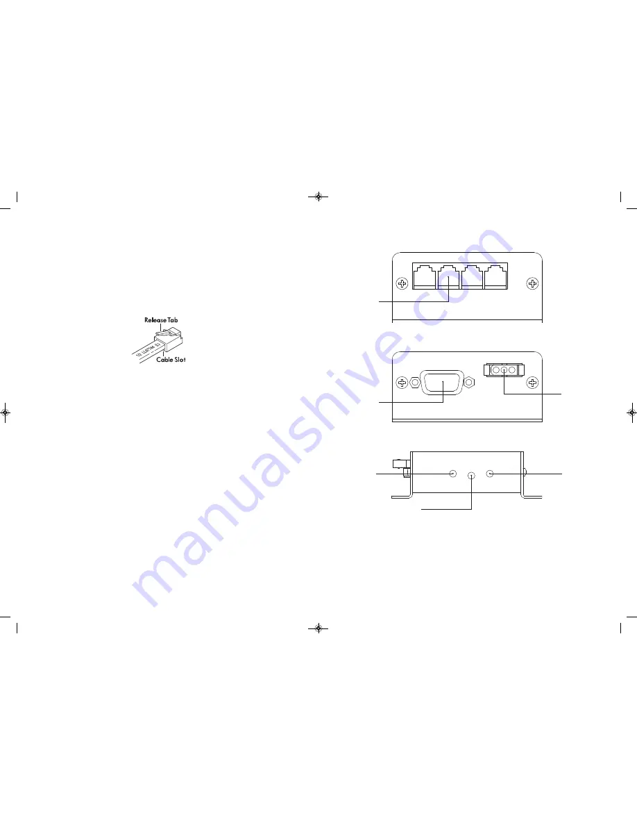
until the release tab on the plug locks into position.
7. Holding the cable so that the printed side of the cable is toward the release
tab on the plug, push the cable into the plug as far as it will go.
8. Note: Always make sure the printed side of the cable is facing the release
tab on the RJ-12 connector plug (Figure 3). This ensures proper orientation
of the plug on each end of the cable.
Figure 3
9. Squeeze the tool handles completely together. You may feel the crimper
finish punching the contacts through the insulation on the wires.
10. Let the handles spring open.
11. Push down on RJ-12 connector release tab (Figure 3) and remove the RJ-12
connector from the crimping tool.
12. Inspect the plug to ensure that the cable is held securely in place.
13. Repeat this procedure as necessary to install a RJ-12 connector plug on each
end of each CA cable.
SON104 600-0240-00 paginated:Layout 1 12/13/11 9:03 AM Page 9


