13
Appendix B - RJ-12 Connector Assembly
RJ Connector, 6 Position Plug Installation
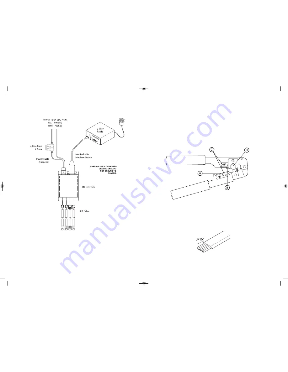
To install the RJ-12 connector plug onto the flat CA cable:
1. Using the cutter blade on the crimping tool
(labeled A, in Figure 1)
, cut the
CA cable so the cut is clean and at a 90-degree angle to the side of the cable.
2. Fully insert one end of the CA cable between the stripping blades
(labeled C,
in Figure 1)
until the end of the cable hits the stop
(labeled B, in Figure 1)
.
Figure 1
3. Squeeze the handles of the crimping tool together until the tool bottoms out.
4. While holding the handles together, pull the cable out of the tool.
5. The stripped insulation should expose approximately 3 /16” of wire
(Figure 2)
.
Figure 2
4
Overview
- Once the intercom is installed, the system is ready for wiring. Headset
modules are connected to the intercom port using RJ-12 connectors and CA cables
as shown in the Figure above. See “CA Cable Routing” in the System Wiring section
of this manual before wiring. A 2-way radio may be added using the 9-pin D-Sub
connector.
System wiring
To Wireless Base Stations
SON104
Intercom
SON104 600-0240-00 paginated:Layout 1 12/13/11 9:03 AM Page 11


