9
ROUTING THE CA CABLES:
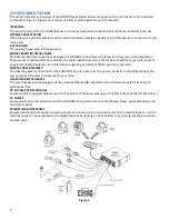
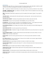
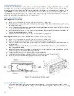
CA cables are flat with six conductors, and may have RJ-12 Modular plugs on each end used to make connections
between the intercom unit and Remote Head.
The path which you intend to run the CA Cables from the Intercom to the Remote Head should also be planned
BEFORE
the installation. The items below are some of the items to consider when planning where to route the CA Cables.
•
Route the CA Cables away from hot surfaces (such as the vehicle exhaust system).
•
Route the CA Cables away from any moving equipment on the vehicle.
•
Route the CA Cables away from the antenna or the antenna cable.
DO NOT
store excess cable. The length of each CA Cable should allow for
approximately 10 inches of excess cable in
each run for service loops (
VERY
IMPORTANT,
especially in installations with a radio operating in the lower
frequencies).
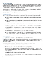
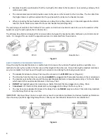
When routing the CA Cables through bulkheads or other sheet metal, use a rubber grommet in the hole to prevent
damage to the cables.
REMOTE HEAD
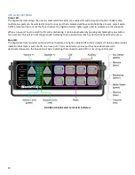
The intercom unit can be remotely controlled by the Remote Head. This panel functions the same as the intercom front
panel. Regardless of which button is pressed, all units will respond and update at the same time. Power to the unit is
supplied through the CA Cable from the Intercom. The Remote Head can be mounted either flush on the apparatus
surface or with a special bracket.
INTERCOM CONNECTIONS:
AUDIO MODULAR JACKS
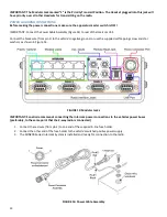
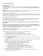
On the rear of the intercom, there are modular jacks under INTERCOM (Figure 4). These are for connecting the CA
Cables from the Headset Jacks or Wireless Bases to the Intercom. All of these modular jacks will provide intercom and
radio communication to the headset positions.
REMOTE MODULAR JACKS
On the rear of the intercom, there is 1 modular jack under REMOTE (Figure 4). This jack is for connecting CA Cables for
the Remote Head. The CA Cables are all the same. Multiple Remote Intercoms can be installed by using an RJ12 splitter.
PRIORITY TRANSMIT
It may be desirable for one member of the crew to have priority for transmitting on the radio. Any headset position
plugged into this jack will have priority for radio transmit over all other headset positions. When the person in this
position presses the PTT on the headset,
ALL
transmissions from any other headset position will be stopped and the
person in the priority position will be able to transmit.
Priority Transmit Assignments:
SON201
: Headset #1 has priority over Headsets 2-6
SON202
: Headset #1 has priority over Headsets 2-8, Headset #2 has priority over Headsets 3-8
SON203
: Headset #1 has priority over Headsets 2-10, Headset #2 has priority over Headsets 3-10, Headset #3 has
priority over Headsets 4-10
SON204
: Headset #1 has priority over Headsets 2-10, Headset #2 has priority over Headsets 3-10, Headset #3 has
priority over Headsets 4-10, Headset #4 has priority over Headsets 5-10
POWER CONNECTIONS
The SON200 Series Intercom requires at least +12 volts DC nominal (with a negative ground) at 1.5 amps. This Intercom
will accept DC voltage as high as 36 volts. The SON200 Series Intercom comes with a Power Cable Assembly and a 1.5
amp, in-line fuse. We suggest connecting the Intercom power and ground to the apparatus power buses.
RADIO INTERFACE
All Radio Interface cables are purchased separately.
IMPORTANT:
ALL connections to the 2-way radio should be performed by a Qualified Radio Technician to ensure proper
interface between the 2-way radio and the SON200 Series Intercom System.


