11
INSTALLATION
BEFORE INSTALLING
the Sonetics SON200 Series Intercoms, make sure you have read and understood the entire
installation procedure. You should also read the sections on Pre-Installation (page 7) and System Orientation (pages 3-5).
If any item in the Installation Procedure is not understood, or if you have any questions which are not addressed in this
manual, contact your local Sonetics Dealer for more information BEFORE you proceed with the installation.
MOUNTING THE INTERCOM:
•
Using the mounting bracket as a template, mark the location of the mounting holes.
•
Using a 3/16" drill bit, drill 2 holes for the #8 sheet metal screws (supplied).
•
IMPORTANT:
Be sure the area behind the panel you are drilling into is free of wires or other obstructions that
could be damaged while drilling the holes
•
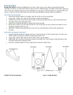
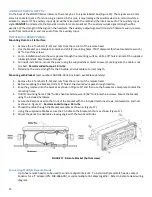
Install the mounting bracket with the sheet metal screws (Figure 8).
•
Remove the 4 screws (2 on each side) closest to the rear of the intercom unit and mount the intercom on the
mounting bracket with the 4 screws.
•
IMPORTANT:
DO NOT completely tighten the intercom mounting hardware until the entire installation is
complete.
MOUNTING THE HEADSET MODULES:
•
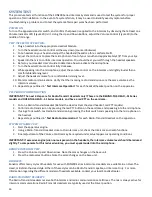
Using the Headset Module as a template (Figure 9), mark the location of the mounting holes. The holes in the
HM-10 used for mounting the module are marked with a letter "M".
•
Using a 5/32" drill bit, drill 2 holes for the #6 sheet metal screws (supplied).
•
IMPORTANT: Be sure the area behind the panel you are drilling into is free of wires or other obstructions that
could be damaged while drilling the holes.
•
Position the Headset Module and secure with the provided sheet metal screws.
FIGURE 8: The Mounting Bracket
Figure 9: Headset Modules


