12
INSTALLING THE CA CABLES: HM-10 MODULE
1.
Slide a Bend-Relief Grommet over one end of the flat CA Cable, small end first.
2.
Attach an RJ-12 Modular Plug to the end of the flat CA Cable (see page 21 for instructions if necessary).
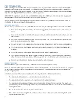
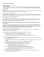
IMPORTANT: ALWAYS make sure the printed side (or smooth side) of the cable is facing away from the release-tab on
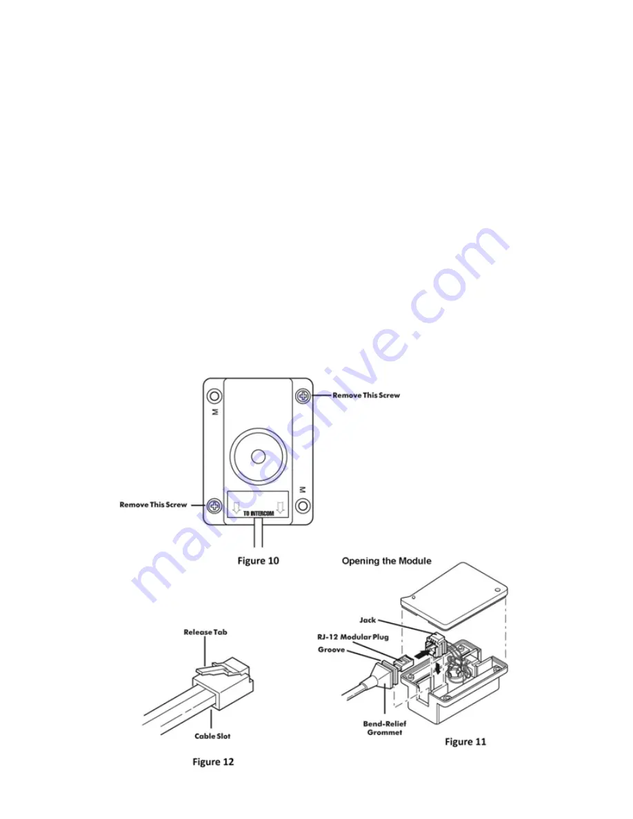
the RJ-12 Modular Plug (Figure 12). This ensures proper orientation of the plug on each end of the cable.
1.
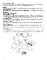
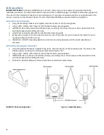
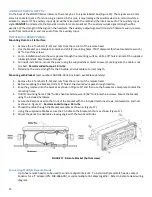
Remove the screws holding the HM-10 together (Figure 10) and remove the bottom plate of the HM-10.
2.
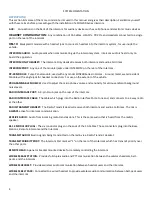
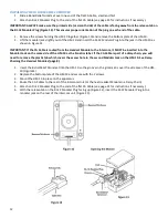
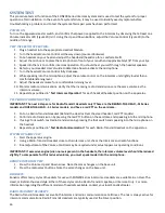
Lift the modular jack slightly out of the HM-10 and insert the RJ-12 Modular Plug into the jack in the HM-10 as
shown in Figure 11.
IMPORTANT: If the CA Cable is routed from the Headset Module to the Intercom, it MUST be inserted into the
Modular Jack on the same side of the HM-10 as the Sonetics label. If the CA Cable is part of a daisy-chain, you will
need to remove the plastic tab which covers the access hole to the second Modular Jack on the HM-10. See Daisy-
Chaining the Headset Modules (page 8).
1.
Insert the Bend-Relief Grommet into the HM-10 so the groove in the grommet is over the side case of the HM-
10 (Figure11).
2.
Replace the bottom plate of the HM-10 and secure with the 2 screws.
3.
Mount the HM-10 in place on the apparatus.
4.
Route the CA Cables to the rear of the Intercom Unit (or the next Headset Module in a Daisy-Chain).
5.
Attach an RJ-12 Modular Plug to the end of the flat CA Cable (see page 21 for instructions if necessary).
6.
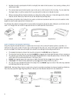
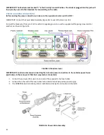
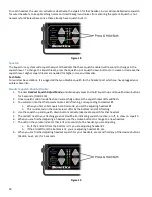
With the release-tab on the RJ-12 Modular Plug facing up (Figure 12), insert the RJ-12 Modular Plug into a
modular jack on the rear of the intercom unit (Figure 13).


