background image


©Copyright 2010-Sonic Air Systems Inc. 

Page 

23

 of 

26


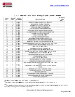
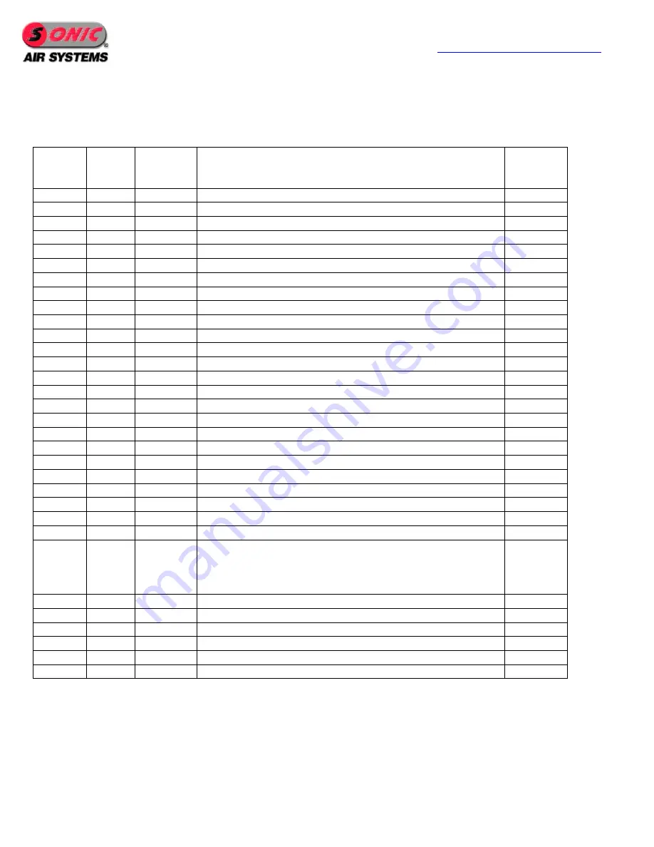
Table 7 - 

PARTS LIST AND TORQUE SPECIFICATION


ITEM  

NO. 

QUAN

TITY 

PART  

NUMBER 

DESCRIPTION 

TORQUE  

FT. LBS. 

(NM) 

16020 

BLOWER HEAD-SONIC 350_PLATED 


12 

10263 

WASHER-1/2" ZINC PLATED 


12699 

SCREW-1/2"-13 X 1 1/2" HHC SS 


12817 

TOOL-350 BELT TENSIONER 


12844 

CLIP-350 BELT TENSIONER TOOL 


12713 

ADAPTER-350 BLOWER HEAD OUTLET 


12826 

CLAMP W/BOLT-6" 350 OUTLET ADAPTER 


11612 

SCREW-6-32 X 1/2" BHS SS 


12816 

TOOL-350 SPROCKET 


10 

12845 

CLIP-350 SPROCKET TOOL 


11 

12678 

BUSHING-45MM SK QD SONIC 350 


12 

12772 

SPROCKET-5.2"OD MOTOR/BLOWER 


13 

14583 

BRACKET-SONIC 350 POWDER PAINTED 


14 

12493 

HANDLE-ROUND PULL 5/16" THK X 1 5/16" W X 4" LG 


15 

14584 

GUARD-SONIC 350 POWDER PAINTED 


16 

12813 

NUT-3/4"-10 HEX ZN PL 


17 

14668 

SCREW-3/4"-10 X 6" HHC ZN PL 


18 

14582 

STAND-SONIC 350 POWDER PAINTED 


19 

14471 

SCREW-1/4"-20 X 3/4" TRUSS HEAD PHILLIPS SS 


20 

12539 

SCREW-5/8"-11 X 1 1/2" HHC ZN PL 


21 

12539 

LOCKWASHER-5/8" HIGH COLLAR SS 


22 

12573 

WASHER-5/8" ZN PL 


23 

12814 

NUT-1/2"-13 HEX ZN PL 


24 

12364 

LOCKWASHER-1/2" ZINC PLATED 


25 

12811 

WASHER-1/2" BEVELED SQUARE 


26 

12944 

MOTOR-BALDOR 50HP STD 326TSC TEFC 3PH 460V 

60HZ  

3500 RPM 11.00" DIA BC C-FACE 1.15 S.F. RIGID 

BASE 


27 

12809 

SCREW-1/2"-13 X 2  1/2" HHC ZN PL 


28 

10490 

SCREW-5/16"-18 X 1 1/4" HHC SS 


29 

12543 

WASHER-5/16" SS 


30 

12789 

STABILIZER-350 BLOWER ZINC PLATED 


31 

12542 

LOCKWASHER-3/8" HIGH COLLAR SS 


32 

12696 

NUT-5/16"-18 HEX SS 


See page 26 for explanations to (*) and (**) and item # 21 

*

use screw P/N 12828 instead of P/N 12808 with motor sprocket P/N 12772 thru 12774


**

for bushing P/N 12674 thru 12677 screw torque value is 30 lb-ft (41Nm); for bushing P/N 12672, 12673 

&12678 screw torque value is 15 lb-ft (20 Nm) 

Summary of Contents for 350

Page 1: ...s Inc Phone 714 255 0124 1050 Beacon Street Fax 714 255 8366 Brea California 92821 www sonicairsystems com Saving Energy Worldwide one PSI at a timeTM Copyright 2010 Sonic Air Systems Inc INSTALLATION AND OPERATION MANUAL SONIC 350 BLOWER ...

Page 2: ...wer Location 9 BLOWER PERFORMANCE INTERFACES 4 The Blower Features 4 Air Filters 4 Airknife Systems 4 Blower Performance 4 Blower Cavitation Surging 5 Blower Interfaces 5 MOTOR WIRING AND START UP 10 BELT INSTALLATION AND TENSION ADJUSTMENT 11 1 Belt and Sprockets Combinations 11 2 Belt Installation 12 3 Sprocket Alignment 14 4 Belt Tension Adjustment 19 SONIC 350 ASSEMBLY 40 50 HP Motors 22 Table...

Page 3: ...prevent belt teeth premature deterioration Refer to motor nameplate data for the proper power supply requirements Make sure the junction box connections are tight and well insulated to prevent shorts and to assure maximum protection against moisture Be sure the motor is electrically grounded and the mounting bolts are secure 1 2 Mechanical Never run the Sonic blower without the belt guard installe...

Page 4: ...e up to 75 F assists in airknife drying Permanent grease lubricated bearings for continuous duty Dual stage impeller in series configuration Steel construction Bracket interface for 40 and 50 HP NEMA and IEC frames At pressures of 3 5 psi airknife velocities can reach 35 000 FPM 2 3 Air Filters For most applications Sonic filter silencer assemblies are standard The filter element is rated to 10 mi...

Page 5: ...ersonnel Discharged air should be silenced to levels required by occupational safety and health standards In order to minimize the pressure drop and noise transmission Sonic recommends the use of smooth bore tubing hard plastic or metal Flex Hose and Sleeves Flex hose can have high pressure drop and should only be used when absolutely necessary Flex hose should be able to handle pressures of 10 PS...

Page 6: ...anufacturer nameplate on the motor Blower Nameplate Each Sonic Blower has a serial number stamped on the nameplate Refer to the packing slip and record blower serial number for future reference on the line below Serial No _________________________ Fig 1 Blower Identification NAMEPLATE ...

Page 7: ...www sonicairsystems com Copyright 2010 Sonic Air Systems Inc Page 7 of 26 Fig 2 Head Mounting Positions POSITION 00 POSITION 06 POSITION 04 POSITION 02 ...

Page 8: ...eye located on the top middle of the housing If the Blower Head Assembly needs replacing it should only be hoisted using 2 lifting straps placed under the Blower cover and hoisted from above The Bracket Bracket Motor Assembly or the Bracket Motor Blower Assembly should only be lifted with a forklift and using the specially designed bracket legs rectangular tubing see Fig 5 During the handling proc...

Page 9: ...ust dirt or other debris will attack the drive belt or clog the filter If the filter needs cleaning or replacing more than one time each month the blower or filter should be moved to a cleaner drier area A Sonic acoustical blower enclosure will also provide additional protection from external influences safe operation Contact Sonic for additional information Wash Down In factory locations subject ...

Page 10: ... belt teeth in shear and of eliminating the electric load bursts that can damage the plant power system Only qualified personnel should perform motor wiring Never run a Sonic centrifugal blower with the discharge open to atmosphere such a situation leads to motor overloading and motor damaging The Sonic 350 blower must rotate counter clockwise CCW when viewed from the sprocket end or clockwise CW ...

Page 11: ... necessary to use the proper QD bushing tapered bushing The tables below give all the part number information applicable to the motor and blower sprockets and QD bushings as well as the drive belt Table 1 Drive Belt Drive Belt Part Number Drive Belt Length MM 12708 1750 Table 2 Blower Sprocket and QD Bushing Sprocket Part Number Sprocket Outside Diameter IN Sprocket Number of Teeth QD Bushing Part...

Page 12: ...used for any particular application the center distance of motor blower sprockets will vary There is only one belt size used for all applications and as a consequence there will be various height positions of the blower relative to the motor 2 5 Loosen the 3 4 hex lock nut of the jack screw mechanism see Fig 9 turn the jack screw counterclockwise to lower the blower to the proper height that will ...

Page 13: ...ms com Copyright 2010 Sonic Air Systems Inc Page 13 of 26 Fig 7 Removing Belt guard Fig 8 Blower Bracket Hex Nuts Fig 9 Jack Screw Hex Nut Fig 10 Belt Sprocket Mesh Jack Screw Jack Screw Nut Blower Bracket Hex Nuts 4 ea ...

Page 14: ...ing 3 No alignment adjustment is necessary after belt replacement 4 No alignment adjustment is necessary after blower sprocket replacement 5 Offset alignment adjustment is necessary after motor sprocket replacement 6 Full alignment adjustment is necessary after either motor or blower replacement 7 Keeping sprockets in good alignment provides good meshing between belt and sprockets reduces vibratio...

Page 15: ...12 Adjustment for misalignment should be done either by modifying motor sprocket position along motor shaft when sprocket face planes are offset relative to one another or by modifying blower position when sprocket face planes are rotated relative to one another All alignment adjustments are done with the belt removed Offset misalignment see Fig 11 the straight edge either interferes equally with ...

Page 16: ...a 3 4 in open wrench on bolt head and a 3 4 in socket on the nut which hold the blower to the bracket support see Fig 15 reposition the blower to correct the misalignment tighten the hex nuts to 48 7 ft lbs and check misalignment To correct angular misalignment along a horizontal axis loosen the four hex screws use a 3 4 in open wrench on bolt head and a 3 4 in socket on the nut holding the blower...

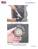
Page 17: ...www sonicairsystems com Copyright 2010 Sonic Air Systems Inc Page 17 of 26 Fig 13 Loosening Motor Sprocket Fig 14 Repositioning Motor QD Bushing on Motor Shaft ...

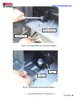
Page 18: ...systems com Copyright 2010 Sonic Air Systems Inc Page 18 of 26 Fig 15 Loosening the Blower on its Bracket Support Fig 16 Shimming Blower Bearing Housing Base Bearing Housing Base Shim Bearing Housing Blower Bracket ...

Page 19: ...page 3 before starting any of the following steps 4 3 Remove belt guard by loosening the six cross recessed head screws holding it to the structure Slide the belt guard away from the structure see Fig 7 4 4 Loosen the four hex bolts 1 1 2 turns do not remove that are locking the blower support bracket to the motor see Fig 8 so that it will easily slide guided by the 4 bolts that are holding it to ...

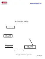
Page 20: ...ems com Copyright 2010 Sonic Air Systems Inc Page 20 of 26 Figure 17B Tension Tool Storage Fig 17C Belt Tensioning Force Measurement Deflected Strand Large O Ring on Scan Scale Straight Edge Small O Ring on Force Scale ...

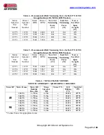
Page 21: ...r Sprocket Part Number Blower Sprocket Part Number Motor RPM Blower RPM New Belt Tensioning Force lbf Used Belt Tensioning Force lbf New or Used Belt Span Length IN 12775 12772 3500 4200 22 16 25 12774 12772 3500 3967 23 16 26 12773 12772 3500 3733 23 17 26 12772 12772 3500 3500 24 17 26 Table 6 NEMA FRAME MOTORS MOTOR SPROCKET QD BUSHING CROSS REF Contact Sonic for appropriate motor Motor HP Moto...

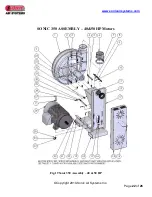
Page 22: ...www sonicairsystems com Copyright 2010 Sonic Air Systems Inc Page 22 of 26 SONIC 350 ASSEMBLY 40 50 HP Motors Fig 19 Sonic 350 Assembly 40 50 HP ...

Page 23: ...3 NUT 3 4 10 HEX ZN PL 17 1 14668 SCREW 3 4 10 X 6 HHC ZN PL 18 1 14582 STAND SONIC 350 POWDER PAINTED 19 6 14471 SCREW 1 4 20 X 3 4 TRUSS HEAD PHILLIPS SS 20 4 12539 SCREW 5 8 11 X 1 1 2 HHC ZN PL 21 4 12539 LOCKWASHER 5 8 HIGH COLLAR SS 22 4 12573 WASHER 5 8 ZN PL 23 8 12814 NUT 1 2 13 HEX ZN PL 24 8 12364 LOCKWASHER 1 2 ZINC PLATED 25 4 12811 WASHER 1 2 BEVELED SQUARE 26 1 12944 MOTOR BALDOR 50...

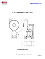
Page 24: ...www sonicairsystems com Copyright 2010 Sonic Air Systems Inc Page 24 of 26 SONIC 350 CENTRIFUGAL BLOWER Nominal Dimensions ...

Page 25: ...ths or 1250 hours Motor Check rubber motor mounts periodically Inspect for cracks Notes Rubber vibration mounts deteriorate over time in ambient conditions Spare mounts are available at Sonic Check motor bearing lubrication every six to twelve months in accordance with motor manufacturer s instructions included with this manual Air Filter Check filters periodically and replace as needed Read the f...

Page 26: ...or sprocket wobbling Motor sprocket out of alignment Sprocket teeth worn Hostile environment belt contaminated Wrong belt not sonic approved Incorrect belt installation method Liquid entering blower inlet impeller stall Electrical overloading Exceeding rated CFM Blower RPM too high motor sprocket too large Motor has winding or bearing damage Electrical supply problems Irregular Excessive Noise Blo...

Reviews: